Pivot locks – Great Plains PH-20 Operator Manual User Manual
Page 18
16
Section 2 Operating Instructions
PH-15, PH-20, PFH-15 and PFH-20 Precision Fertilizer Hitch 148-365M
12/29/2011
Great Plains Mfg., Inc.
By watching the manifold pressure when operating at
field speeds, you can confirm that you have the cor-
rect orifice plates needed to keep the manifold pres-
sure between 5 psi and 85 psi. If the gauge reads
below 5 psi or above 85 psi, use different orifice
plates.
If the gauge reading increases slowly over time, check
for plugging at the orifice plate(s) under the quick
cap(s) or at the nozzle behind the coulter blade. If the
gauge reading drops suddenly, check for empty tanks,
or a disconnected pump supply hose.
Marker Option
Optional marker attachments are available from your
Great Plains dealer. Before operating markers, make sure
hydraulics have been bled properly.
The dual markers are equipped with a sequence valve and
are powered off one hydraulic circuit. Starting with both
markers folded, the folding sequence is:
1. Activate lever – Right unfolds; left stays folded.
2. Reverse lever – Right folds up; left stays folded.
3. Activate lever – Left unfolds; right stays folded.
4. Reverse lever – Left folds up; right stays folded.
5. Sequence repeats.
You can adjust marker folding speed. Refer to Marker Ad-
justments, “Adjustments,” page 28, and adjust folding
speed to a safe rate. Folding markers at high speed can
damage markers.
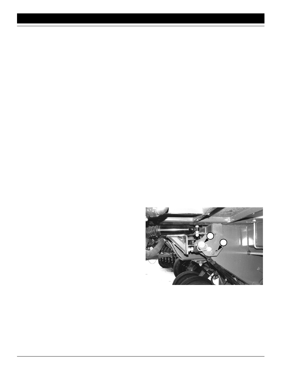
Pivot Locks
Pivot-locks are located in front of the transport frame. The
tubes provide stability during hitch transport. When hitch
is raised, pivot-lock tubes rotate down to restrict hitch piv-
oting. When hitch is lowered, pivot-lock tubes rotate up
and allow hitch and frame to pivot freely in the field.
In most field conditions, allow pivot-lock tubes to raise and
lower automatically. Store pin shown in Figure 2-1 in its
storage hole (1).
When planting on steep slopes or when backing hitch dur-
ing hookup, up may need to lock the tubes for increased
stability. To lock tubes, insert pin over lowered tubes (2) as
shown in Figure 2-1.
Figure 2-1
Pivot Lock
You can adjust spring tension on pivot-lock tubes. Refer to
Pivot Lock Adjustment, “Adjustments,” page 29.
18133
1
2