Hooking up hydraulic hoses – Great Plains PH-20 Operator Manual User Manual
Page 12
10
Section 1 Preparation and Setup
PH-15, PH-20, PFH-15 and PFH-20 Precision Fertilizer Hitch 148-365M
12/29/2011
Great Plains Mfg., Inc.
3.
Position quick-hitch handles to locking position as
shown in Figure 1-5. This will allow drill hitch pins to
snap into quick-hitch links and secure drill to hitch.
Figure 1-5
Hitch Link
4.
Position hitch in front of drill so quick-hitch links on
hitch are in line with lower hitch pins on drill. Hydrauli-
cally retract transport-lift cylinders to position quick-
hitch links slightly lower than drill hitch pins.
5.
Back hitch up to drill until hitch pins contact quick
hitch. Hydraulically raise hitch just until drill hitch pins
are secure inside quick-hitch links. Do not raise drill
any higher than necessary.
6.
Visually confirm that pins are seated and latches have
snapped out over the pins.
7.
Attach slotted link bar (1) to top hitch extension on
drill. Use 1-by-3 3/4-inch pin (2) and bushing (3) to pin
level-link bar to drill. Secure pin with clip provided (4).
See Figure 1-6.
Figure 1-6
Top Hitch Link and Drill Extension
18117
12086
Hooking Up Hydraulic Hoses
Escaping fluid under pressure can have sufficient force to pene-
trate the skin. Check all hydraulic lines and hoses before apply-
ing pressure. Fluid escaping from a very small hole can be
almost invisible. Use paper or cardboard, not body parts, to
check for suspected leaks. If injured, seek medical assistance
from a doctor that is familiar with this kind of injury. Foreign
fluids in the tissue must be surgically removed within a few
hours or gangrene will result.
Great Plains hydraulic hoses are color coded to help you
hookup hoses to your tractor outlets. Hoses that go to the
same remote valve are marked with the same color.
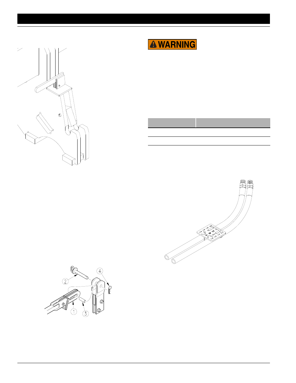
To distinguish hoses on the same hydraulic circuit, refer to
plastic hose holder. See Figure 1-7. Hose under extend-
ed-cylinder symbol feeds cylinder base ends. Hose under
retracted-cylinder symbol feeds cylinder rod ends.
Figure 1-7
Hydraulic Hose Color Ties
NOTE: If your implement is equipped with the optional
Coulter Command system, refer to Coulter Command
Hookup, page 11, for instructions on hydraulic hookup.
1.
Connect hydraulic hoses from tongue cylinder to one
set of tractor outlets.
2.
Connect hoses from transport-lift cylinders to another
set of tractor outlets.
3.
Connect hoses from optional markers to a third set of
tractor outlets.
Color
Hydraulic Function
Red
Tongue Cylinder
Blue
Transport Lift Cylinders
Orange
Marker Cylinders
17641