Prestart checklist, Field operation – Great Plains PH-20 Operator Manual User Manual
Page 15
13
Section 2 Operating Instructions
12/29/2011
PH-15, PH-20, PFH-15 and PFH-20 Precision Fertilizer Hitch 148-365M
Great Plains Mfg., Inc.
Section 2
Operating Instructions
This section covers general operating procedures. Experi-
ence, machine familiarity and the following information will
lead to efficient operation and good working habits. Al-
ways operate farm machinery with safety in mind.
Prestart Checklist
1.
Carefully read “Important Safety Information,” be-
ginning on page 1.
2.
Lubricate implement as indicated under Lubrication,
“Maintenance and Lubrication,” page 33.
3.
Check all tires for proper inflation as indicated on Tire
Inflation Chart, “Appendix,” page 40.
4.
Check all bolts, pins and fasteners. Torque as speci-
fied on Torque Values Chart, “Appendix,” page 40.
5.
Check implement for worn or damaged parts. Repair
or replace before going to the field.
6.
Check hydraulic hoses, fittings and cylinders for leaks.
Repair or replace before going to the field.
Field Operation
You may be severely injured or killed by being crushed between
the tractor and hitch. Do not stand or place any part of your
body between hitch and moving tractor. Stop tractor engine and
set park brake before installing the hitch pin.
Escaping fluid under pressure can have sufficient force to pene-
trate the skin. Check all hydraulic lines and hoses before apply-
ing pressure. Fluid escaping from a very small hole can be
almost invisible. Use paper or cardboard, not body parts, to
check for suspected leaks. If injured, seek medical assistance
from a doctor that is familiar with this kind of injury. Foreign
fluids in the tissue must be surgically removed within a few
hours or gangrene will result.
1.
Hook hitch to a suitable tractor and drill. Refer to
Hooking Hitch to Tractor and Hooking Hitch to Drill,
“Preparation and Setup,” page 8.
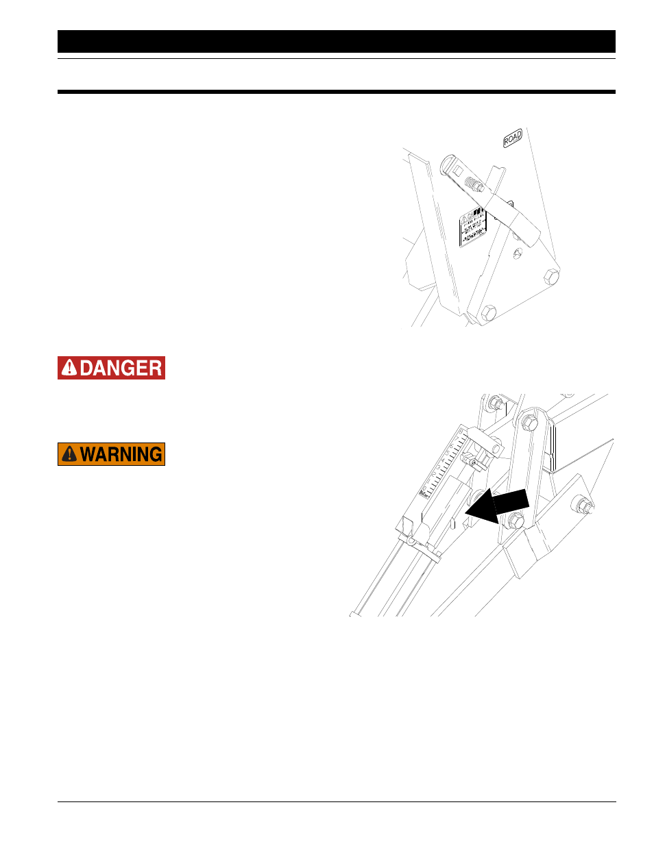
2.
Move transport-lock handle to field position. See Fig-
ure 2-1.
Figure 2-1
Transport-Lock Handle, Field Position
3.
Remove cylinder lock channel from tongue cylinder.
See Figure 2-2.
Figure 2-2
Cylinder Lock Channel
12330
12483