Great Plains 3S-5000HDF Operator Manual User Manual
Page 51
Great Plains Manufacturing, Inc.
Adjustments
47
2012-08-14
195-325M
Table at right shows the approximate force at openers for
a given pressure at the pressure control valve.
Note: To account for additional compaction from drill and
tractor tires, set pressure on center openers slightly
higher than wing openers.
To run the drill with constant opener down pressure
requires an Active Hydraulic System. An Active Hydraulic
System requires a tractor with closed-center hydraulics
or pressure/flow compensated hydraulics powered by a
variable displacement hydraulic pump. (If you are not
familiar with your tractor’s hydraulics, consult your tractor
dealer.)
Tractors with load-sensing hydraulics must use the bypass
valve to operate the 3S-5000/F/HD/HDF. Failure to use the
bypass valve can cause major tractor damage. Before
adjusting opener down pressure, set bypass valve as explained
under “Setting the Bypass Valve” on page 26.
Note: To run the drill on tractors with open-center
hydraulics or on tractors with fixed displacement
hydraulic pumps you must install a Great Plains kit,
part number 194-143A. Contact your Great Plains
dealer for ordering information. See “Non-Active
Hydraulic System” on page 30.
To set down pressure:
1.
Lower openers to the ground. Lock hydraulic lever
forward for constant hydraulic flow.
You must lock hydraulic lever forward. See “Opener
Operation” on page 28, for instructions.
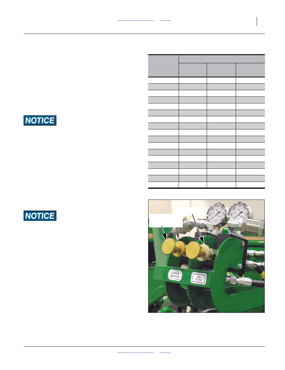
Refer to Figure 43
2.
Turn knob on pressure-control valve while watching
pressure gauge, turn knob until gauge shows
desired pressure. Turn clockwise to increase
pressure. Turn counterclockwise to decrease
pressure.
There is one pressure-control valve for openers on
the center section and one for openers on the wing
sections of the drill.
As a general starting point, set hydraulic down
pressure to 1000 psi. For most field conditions,
adjust down pressure between 200 and 1600 psi.
Hydraulic Down-Force
Gauge
Setting
Pounds of Force at Opener Disks
6 inch
rows
7
1
⁄
2
inch
rows
10 inch
rows
200 PSI
83
86
92
300 PSI
90
95
102
400 PSI
97
103
113
500 PSI
103
111
124
600 PSI
110
119
135
700 PSI
117
128
146
800 PSI
123
136
157
900 PSI
130
144
167
1000 PSI
137
152
178
1100 PSI
143
161
189
1200 PSI
150
169
200
1300 PSI
157
177
211
1400 PSI
163
185
222
1500 PSI
170
194
233
1600 PSI
176
202
244
1700 PSI
183
210
254
1800 PSI
190
218
264
Figure 43
Pressure Control Valves
34293
Adjustment
Knob
Lock Disk