Electric drive transfer assembly – Wheatheart Transfer Auger User Manual
Page 22
3. A
SSEMBLY
W
HEATHEART
M
ANUFACTURING
- T
RANSFER
A
UGER
3.2. H
YDRAULIC
D
RIVE
T
RANSFER
A
SSEMBLY
8”, 10”, & 13”
22
IM2 R2
3.3. ELECTRIC DRIVE TRANSFER ASSEMBLY
Refer to Figure 3.9 and 3.10 for assembly of Transfer Augers with electric drive
kits.
Note: Belts and pulleys NOT provided. You must supply your own.
1. Install wheel frame clamp top and bottom (5) to tube (1) but don’t tighten,
(see Figure 3.9) and secure with four 5/16" x 1-1/2" bolts (6) and locknuts (7).
2. Attach
u-joint to hopper auger.
3. Attach upper tube (1) to hopper bottom (2) with seven 7/16" x 1-1/4" bolts (8),
flat washers (9), and nuts (10). When installing bolts, also attach frame
brackets (11) to hopper as shown in Figure 3.9.
Note:
Use flat washers on both sides of hopper/tube.
4. Attach upper (3) and lower (4) support tubes to axle (12) by sliding over axle
shaft.
5. Mount each tire and rim (13) on axle and secure with cotter pin (15) and flat
washer (14).
6. Install
upper
support tubes (3) to wheel frame clamp (13) with two 1/2" x
1-1/2" bolts (6) and 1/2" locknuts (7).
7. Install lower support tubes (4) to lower frame brackets (11) with two 1/2" x 1-
1/2" bolts (16) and 1/2" locknuts (17). Adjust tube clamp until hopper is off
ground ~1/2" (1.27 cm) and tighten.
8. Install 1/4” x 1-1/2” key (19) on electric motor shaft (20) and mount drive
pulley (21) on shaft.
Note:
Drive pulley should be 3.75" - 4.25"; see Figure 3.10.
9. Install 1/4” x 1-1/2” key (25) on flighting shaft (26) and mount pulley (27) on
shaft.
10. Insert motor mount plate (28) with hex nuts (29) into head plate (24).
11. Place the electric motor (20) on the mount (28), and using a level or straight
edge, align the ends of the flighting shaft (26) and motor shaft (20).
12. Use c-clamps or vice grips to temporarily secure the motor to the mount.
13. Mark hole locations on the motor mount and remove the motor and clamps /
vice grips. Drill holes through to match the size of the mounting bolts, and
install motor using bolts and locknuts.
14. Install the belts (30) (NOT PROVIDED). The belts should deflect 1/2" to 3/4"
when pushed on with a 5 lb force. If they do not deflect properly, tighten or
loosen the hex nuts (29) on the mount plate until the belt tension is adequate.
15. Secure pulley guard (31) to transfer handle tabs (32) with two bolts (33) and
3/8” locknuts (34).
Important:
Final rpm for the auger should be between 500-600. Example: for 1750 rpm,
using a 3.75" motor pulley, 12.7" auger pulley, final rpm = 517.
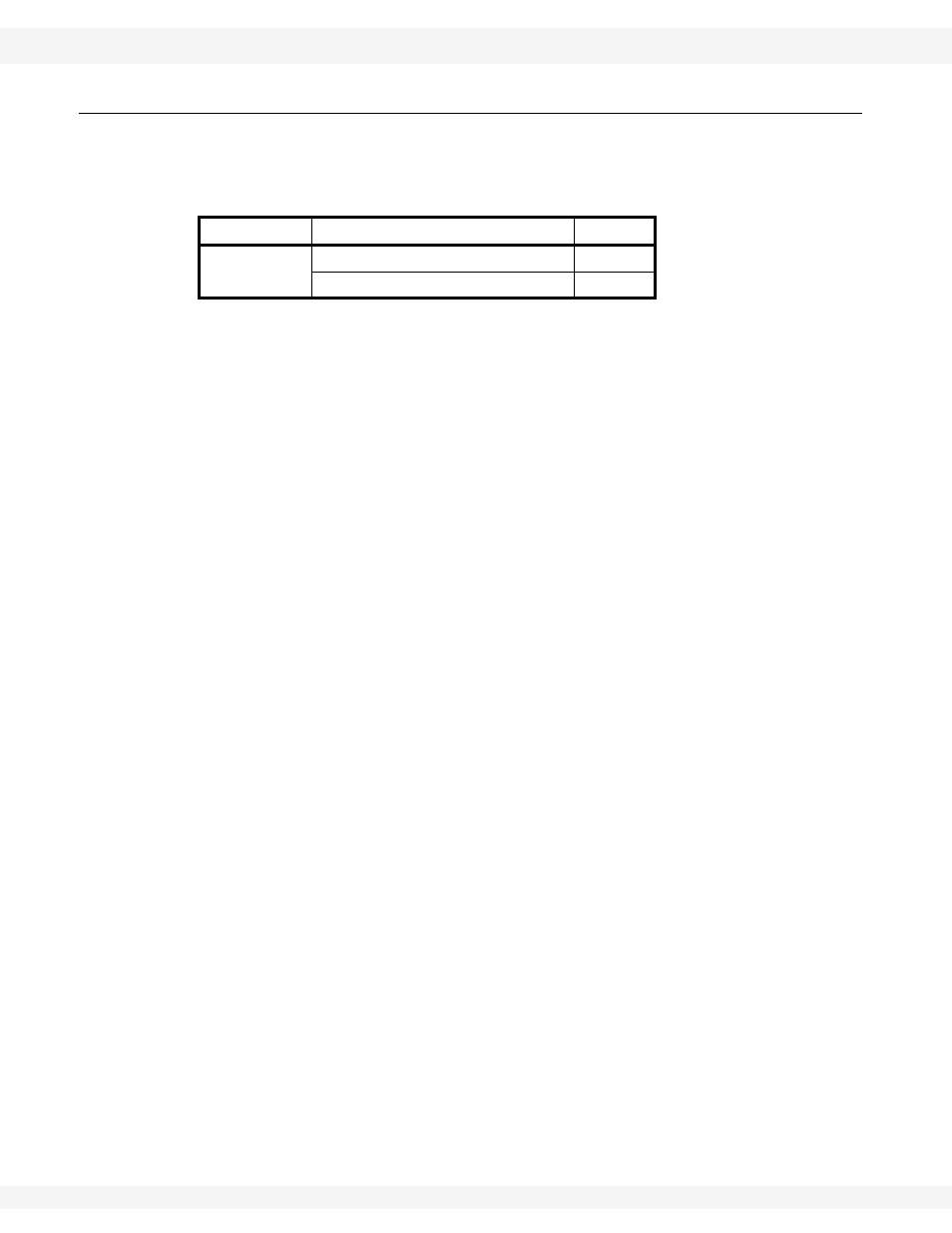
AUGER SIZE
Description
QTY.
10”
B55 BELT
2
4.2” PULLEY
1