L valve (see figure 3.6), S (30). refer to figure 3.6 – Wheatheart Transfer Auger User Manual
Page 20
3. A
SSEMBLY
W
HEATHEART
M
ANUFACTURING
- T
RANSFER
A
UGER
3.2. H
YDRAULIC
D
RIVE
T
RANSFER
A
SSEMBLY
8”, 10”, & 13”
20
IM2 R2
4. Attach upper (33) and
lower (32) support
tubes to axle (34) by
sliding over axle shaft.
5. Mount tire and rim (35)
on axle (34) and secure
with cotter pin (37) and
3/4" flat washer (36).
6. Install upper support
tubes (33) to tube
support (25) with a
1/2" x 6" bolt (38), 1/2"
flat washer (40), and
1/2" locknut (39).
7. Install lower support tube (32) to tube support (25) with two
3/8" x 1-1/4" bolts (41), 3/8" flat washers (43), and 3/8" locknuts (42).
H
YDRAULIC
D
OUBLE
D
RIVES
(10")
1. Connect the long hydraulic hoses (1 and 2) to the hopper hydraulic motor
(11). Run these hoses (1 and 2) through the hopper guard (D). Refer to
Figure 3.8.
2. Open center hydraulics only: Place the ball valve (4) on the handle (9) of
the transfer auger. Connect hose (1) to part (5B) of the valve. Place the swivel
fittings (12,14) into the ports of the tube hydraulic motor (8). Connect hose (2)
to the swivel fitting (12) of the hydraulic motor (see Figure 3.8). Join the short
hydraulic hose (3) into the swivel fitting (14) of the hydraulic motor. Place the
other end of the short hose (3) into the port (5A) of the valve. Next, secure the
hoses (1 and 2) to the tube. (See Figure 3.8.)
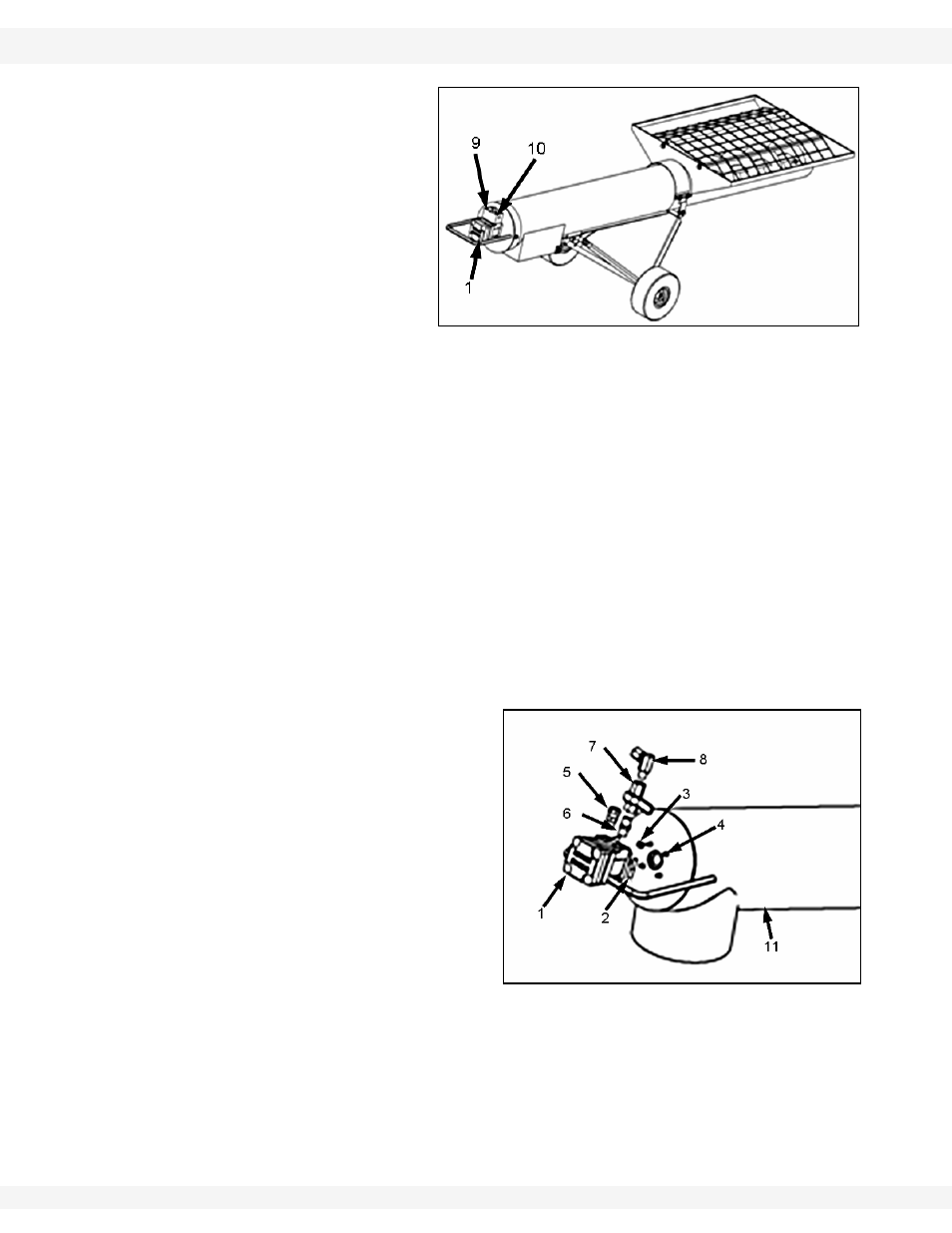
3. For 10” and 13” closed center
hydraulics only: Install 1/2”
nipple (6), 1/2” ball valve (7),
and 1/2” elbow (8) on pressure
side, and 1/2” swivel (5) on
return side (see Figure 3.7).
4. Closed center hydraulics only: Attach hydraulic line (13) to elbow. Connect
hose (2) to the swivel fitting (7) on the hydraulic motor (8). Secure hoses (1
and 2) to the tube. (See Figure 3.8.)
Figure 3.6
Figure 3.7