Wheatheart Transfer Auger User Manual
Page 19
W
HEATHEART
M
ANUFACTURING
- T
RANSFER
A
UGER
3. A
SSEMBLY
8”, 10”, & 13”
3.2. H
YDRAULIC
D
RIVE
T
RANSFER
A
SSEMBLY
IM2 R2
19
2. Install a control valve (9) onto the hydraulic motor using the 5/16” Allen head
bolts (10). Install hydraulic fittings into the control valve (see Figure 3.6).
8”, 10”,
AND
13”
MODELS
:
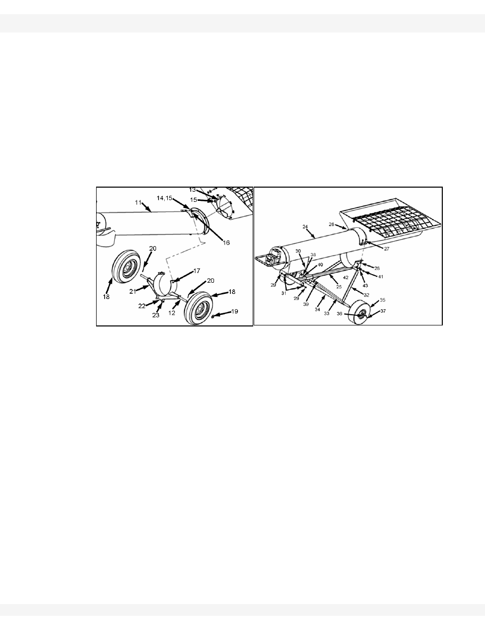
1. Attach axle (12) to tube (11) with four 5/16" x 1-1/2" bolts (16) and locknuts
(17) (see Figure 3.5 A). Locate the axle band so that the hopper is 1/2" (1.27
cm) off the ground.
2. Install frame stiffeners (21) on axle (12) and secure with bolt (22) and locknut
(23).
3. Place wheels (18) on axle (12) and anchor each with a 3/4" washer (19) and
cotter pin (20).
4. Refer to Figure 3.5 B for the poly transfer frame assembly.
P
OLY
M
ODEL
1. Remove the plate protecting the top of the hydraulic motor and place #112 o-
rings into the recessions in the top of the hydraulic motor.
2. Install a control valve (9) onto the hydraulic motor using the 5/16” Allen head
bolts (10). Install hydraulic fittings into the control valve (see Figure
3.6).Connect upper end of tube support (25) to tube (24) with two 3/8" x 1-1/
4" bolts (29), 3/8" flat washers (31), and 3/8" locknuts (30). Refer to Figure
3.6.
3. Connect lower end of tube support (25) to tube (24) with tube clamp (26),
bolts (27), and locknuts (28).
Figure 3.5 A
B