Assembly, Gas drive transfer assembly – Wheatheart Transfer Auger User Manual
Page 15
W
HEATHEART
M
ANUFACTURING
- T
RANSFER
A
UGER
3. A
SSEMBLY
8”, 10”, & 13”
3.1. G
AS
D
RIVE
T
RANSFER
A
SSEMBLY
IM2 R2
15
3. Assembly
Augers are available in various combinations. In most cases, the following
instructions will apply to all augers. Where the information varies, additional
instructions will be included, indicated by an arrow.
3.1. GAS DRIVE TRANSFER ASSEMBLY
Refer to Figure 3.1, 3.2, 3.3, and 3.4 for assembly of Transfer Augers with gas
drives.
Note: Belts and pulleys NOT provided. You must supply your own.
1. Secure spout (1) on stands to aid in assembly.
2. Attach motor mount top and bottom clamps (2) to tube (1) 15" (38.1 cm) from
the spout (see Figure 3.1) using eight 5/16" x 1-1/4" bolts (3) and locknuts
(4). Use a level to ensure mount is parallel to the ground before tightening.
3. Position
plate (5) on motor mount (2) using pin (6), 3/4" flat washer (7), and
hairpin (8) to secure in place.
4. Insert
tightener
pin (9) in mount and secure with 1/2" flat washer (10) and
hairpin (11).
5. Remove spout (1) from stands.
6. Couple upper and lower flighting together with a u-joint (15) and secure each
side with a 3/8" x 2-1/4" bolt (16) and locknut (17) (Figure 3.2 and 3.3).
Note:
U-joint is pre-assembled on upper tube flighting.
7. Attach upper tube (1) to hopper bottom (19) with seven 7/16" x 1-1/4" bolts
(20), flat washers (21), and nuts (22).
Note:
Use flat washers on both sides of hopper/tube.
8. Attach
upper
(23) and lower (24) support tubes to axle (25) by sliding over
axle shaft.
9. Mount each tire and rim (44) on axle and secure with cotter pin (46) and flat
washer (45).
10. Attach upper support tubes (23) to motor mount bottom clamp (2) with two
1/2" x 2" bolts (26) and locknuts (27).
Warning: Before continuing, ensure you have read and understand the relevant information
in the safety section. Safety information is provided to help prevent serious injury, death, or
property damage.
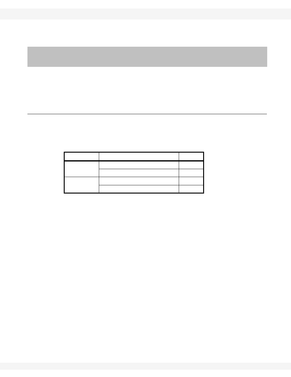
AUGER SIZE
Description
QTY.
8”
B70 BELT
1
3” X 3/4” BORE PULLEY
1
10”
B70 BELT
1
3-3/4” X 1” BORE PULLEY
1