Hydraulic drive transfer assembly, 4 for assembly of transfer augers with, Figure 3.4 – Wheatheart Transfer Auger User Manual
Page 18
3. A
SSEMBLY
W
HEATHEART
M
ANUFACTURING
- T
RANSFER
A
UGER
3.2. H
YDRAULIC
D
RIVE
T
RANSFER
A
SSEMBLY
8”, 10”, & 13”
18
IM2 R2
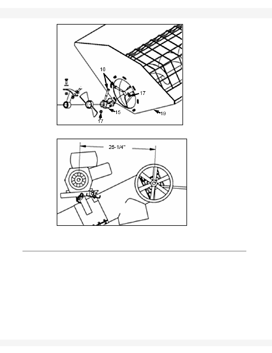
Figure 3.3
Figure 3.4
3.2. HYDRAULIC DRIVE TRANSFER ASSEMBLY
Refer to Figure 3.5 – 3.8 for assembly of Transfer Augers with hydraulic drive
kits.
1. Insert a 3/8” x 2” bolt (2) through the hydraulic motor shaft (1) and secure to
upper auger shaft with a 3/8” locknut (3).
2. Mount hydraulic motor (1) to upper auger tube using four 3/8” x 3/4” bolts (4).
Note:
Install bolts through tube end plate from inside.
8"
MODEL
:
1. Remove the plate protecting the top of the hydraulic motor and place #112 o-
rings into the recessions in the top of the hydraulic motor.