OSRAM SYLVANIA ENCELIUM User Manual
Page 2
76-017-DB 11/13
OSRAM and Logo are registered trademarks of OSRAM GmbH.
ENCELIUM and Polaris 3D are registered trademarks of OSRAM SYLVANIA, Inc
GreenBus II are trademarks of OSRAM SYLVANIA, Inc.
SEE THE WORLD IN A NEW LIGHT is a registered trademark of OSRAM SYLVANIA, Inc.
Communication Circuit (24VDC, Class 2)
GreenBus II
TM
is a low-cost, high reliability communication means to report sensor information back to
the ENCELIUM Energy Management System and to obtain optimum brightness settings for each
individual light fixture from the system – optimized to result in minimum energy costs for any given
building.
The GreenBus II
TM
wiring originates at an Energy Control Unit (ECU) and propagates in a daisy-chain or
“T” fashion from module to module (or other compatible equipment).
GreenBus II
TM
uses proprietary connectors and jacks for ease of installation only.
GreenBus II
TM
is a proprietary standard. Connect to ENCELIUM Energy Management System
only. Do not connect to other circuits.
Connect to ENCELIUM Energy Management System only. Do not connect to other circuits.
Maximum 100 total devices
GreenBus II
TM
must be laid out as per ENCELIUM EMS supplied drawing. If changes are required,
determine an optimum wiring path utilizing the supplied prefabricated cables, based on the position of
light fixtures and sensors. As the modules obtain power via the GreenBus II
TM
, the number of modules
on each chain is limited. It is suggested to leave room for future system upgrades and to limit the
number of modules per chain to 100 units during initial installation.
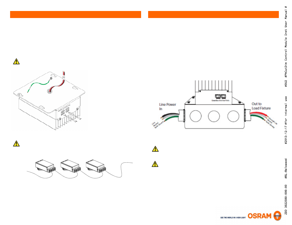
In a typical installation, Phase Cut Dimming Modules connect to Incandescent/Halogen lamps,
Fluorescent ballasts, LED fixtures, and LED/CF lamps that are capable of being dimmed via phase cut
method (forward and reverse phase).
The Phase Cut Dimming Module is typically connected to an individual or group of fixtures/lamps.
The mechanical construction allows for simple installation of the Phase Cut Dimming Module on top of a
standard square 4 11/16” junction box. Only a 4 11/16” junction box can be used, as the mounting
holes on the Phase Cut Dimming Module properly align with the holes on the junction box. ENCELIUM
GreenBus II™ communication wiring is still accessible from the outside of the junction box, while all
necessary wiring to the load (single or multiple ballasts/ LED fixtures) is done on the inside.
Wire as shown. Refer to local code, etc.
Refer to local code, etc.
Refer to local code, etc.
Refer to local code, etc.
Absolute maximum load ratings
120VAC: 450W, 3.8A max
277VAC: 900W, 3.3A max
Due to the internal relay, power feed to module may be live even if lights are off. Turn off
power at circuit breaker or fuse before installing or servicing module. Observe lockout
procedures.
GreenBus II™ Wiring
GreenBus II
TM
Communication
(Communication Circuit, Low Voltage)
Black – Line in
White – Neutral
Red – Relay output & Dim Control (connect to load)
Relay Contact; recommended relay
switching capacity 120VAC, 450W or
277VAC, 900W maximum
Phase Cut Dimming Module Installation
Earth Ground