Exide Technologies V19CIL5200ULF User Manual
Page 12
Sales
•
Service
•
Recycling 888.563.6300 in the USA 800.268.2698 in Canada
11
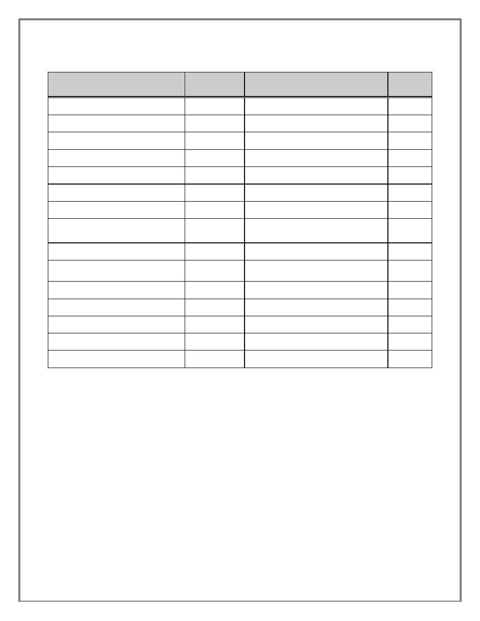
10. FLX200 STANDARD CHARGER OPERATION
CHARGE CONDITION
DISPLAY
DEFAULT
FUNCTION BUTTON DISPLAY SELECTION
LED
I1
A A,V,Ah,t,Ph
Y*
CONSTANT VOLTAGE
A/ #StSt
A,V,Ah,t,Ph
Y
I2
A A,V,Ah,t,Ph
Y
COOL DOWN PERIOD
CooL / rt
A,V,Ah,t,tr
G*
TERMINATION
rEdy A,V,Ah,t,tr
G
TERMINATION/ FAULT CODE
rEdy / F
A,V,Ah,T,tr
R*, G
REFRESH CHARGE
A / rEFr
A,V,Ah,t,tr
G, Y
SETTING EQUALISE
EqAL
for 5 seconds then default display
Charge
stage
EQUALISE CHARGE
A / EqAL
A,V,Ah,t,tr
G*, Y
AUTO BALANCE
StSt / A StSt / V
A,V,Ah,t,tr
G
Lobt CHARGE PERIOD
Lobt / A
A,V,Ah,t
Y*
Lobt OFF PERIOD
Lobt / V
A,V,Ah,t
CRITICAL FAULT CODE
F
R
NONE CRITICAL FAULT CODE
F
Charge continues
R*
DELAYED START OF CHARGE
dELy / rt
A
= Output current
V
= Volts per cell
Ah
= Returned ampere hours
t
= Time of recharge
F
= Fault code, display will alternate with the two codes
Ph
= Phase of charge i.e. 1, 2 and 3
StSt
= Smart start
Cool
= Cool down period
LoBt
= low battery override
/
= Display will alternate with the two-displayed information
rt
= Remaining time
tr
= Termination method, tr1 = dv/dt, tr2 = I2 entered 3.5 hour timer operated
tr3 = Constant voltage stage entered 3.5 hour timer operated, tr4 = di/dt.
tr5 = Smart Start, tr6 = Autobalance timeout
* = flashing LED.
NOTE: In LoBt, StSt, Equalise and Termination charge function display will only be displayed for 10 seconds, not
permanently.
# Display if due to smart start.
R: Red
=
Fault, flashing red is a none critical fault.
Y: Yellow
=
Current flowing, flashing yellow when < 2.37VPC.
G: Green
=
charge complete.