CCI Thermal Technologies CPXD - Control Panel for XDF Duct Heater User Manual
Page 2
5.2 INSTALLATION
5.2.1 The heater is designed for installation in a horizontal duct
with the terminal boxes at the side. Improper orientation of the duct
heater could effect the safe and reliable operation of the heater.
IMPROPER ORIENTATION OF THE HEATER
COULD AFFECT THE SAFE AND RELIABLE
OPERATION OF THE HEATER.
NEVER USE THE CONTROL HOUSINGS FOR
LIFTING OR MOVING THE HEATER AS THIS
COULD DAMAGE THE HEATING ELEMENTS AND
CONDUIT.
5.2.2 To install the heater, bolt the heater assembly into the
customer supplied ducting system. If necessary, reinforce with duct
supports to support the heater weight as shown in Table 1.
Note proper orientation of heater, as shown by the “TOP” and
“AIRFLOW” labels.
5.2.3 An explosion-proof pressure differential switch has been
supplied loose. Install the switch in a suitable location and with
proper orientation. Install tubing between the switch and the duct
using the appropriate port on the switch body (sensing high or low
pressure). Consult manufacturer’s operation instructions included
with this manual.
THE PRESSURE DIFFERENTIAL SWITCH IS A
CRITICAL SAFETY COMPONENT. IMPROPER
INSTALLATION OF THE SWITCH MAY RESULT IN
HAZARDOUS CONDITIONS.
4.3 Verify that the nameplate voltage, phase, and wattage are as
ordered and are the same as the electrical power supply available.
DO NOT CONNECT THE HEATER TO AN
ELECTRICAL SUPPLY VOLTAGE OTHER THAN
THAT SHOWN ON THE PRODUCT NAMEPLATE.
REVIEW THIS MANUAL AND ALL DRAWINGS
CONTAINED WITHIN PRIOR TO INSTALLATION,
WIRING, OR OPERATION OF THE HEATER.
5.0 DIMENSIONS AND INSTALLATION
The heater must be installed by qualified personnel in strict
compliance with the electrical code and hazardous locations
standards.
THE HEATER MUST BE INSTALLED IN A
HORIZONTAL DUCT SECTION ONLY. IMPROPER
ORIENTATION OF THE HEATER COULD AFFECT
THE SAFE AND RELIABLE OPERATION OF THE
HEATER.
5.1 HEATER DIMENSIONS
MI289 REV.2.01 Page 2 of 4
CCI Thermal Technologies Inc. 2721 Plymouth Drive, Oakville, ON L6H 5R5 Tel. (905) 829-4422 Fax (905) 829-4430
www.ccithermal.com
Page 2 of 4
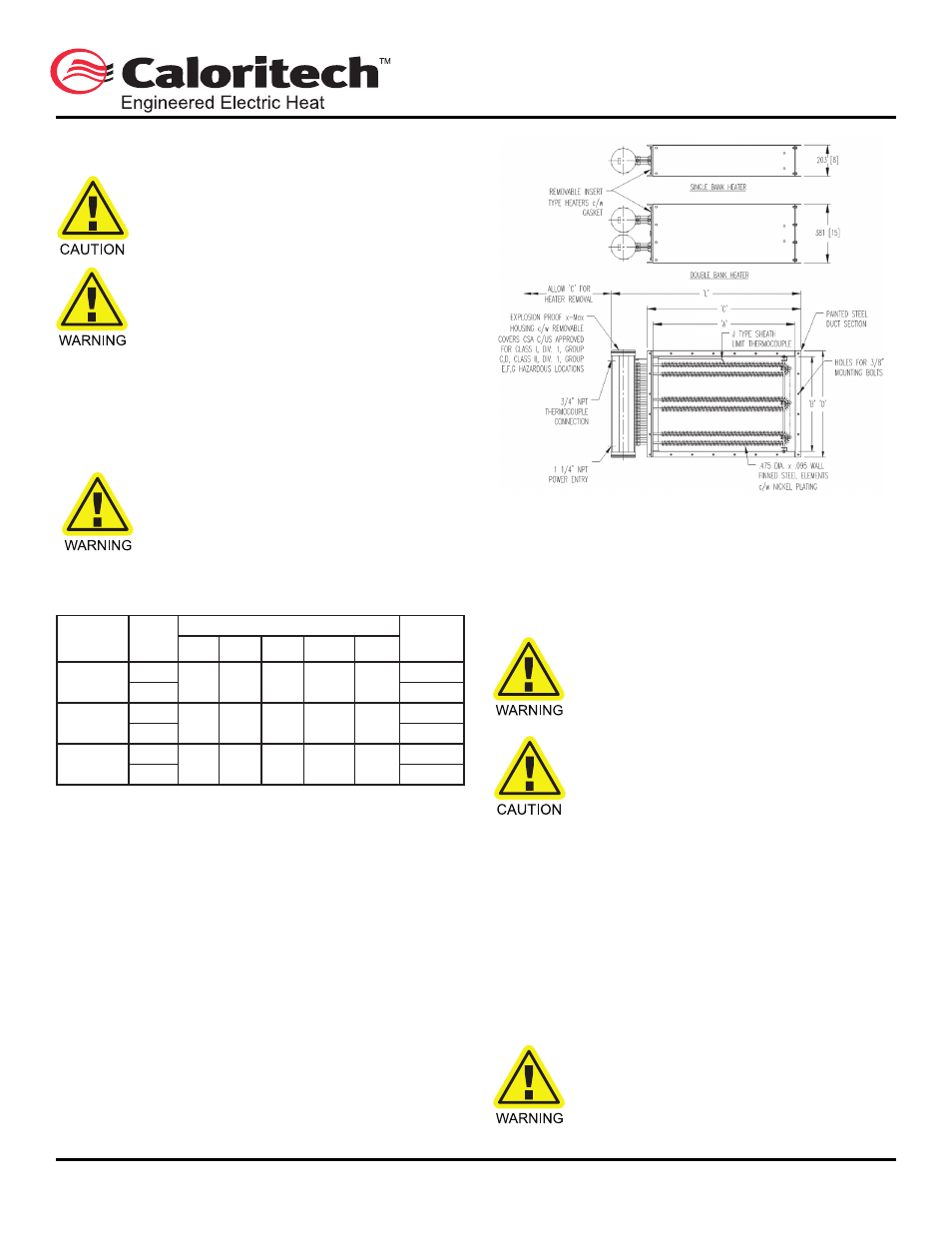
Figure 1 - XDF Heater Dimensions
5.2
INSTALLATION
5.2.1 The heater is designed for installation in a horizontal duct
with the terminal boxes at the side. Improper orientation of the
duct heater could effect the safe and reliable operation of the heater.
IMPROPER ORIENTATION OF THE HEATER
COULD AFFECT THE SAFE AND RELIABLE
OPERATION OF THE HEATER.
NEVER USE THE CONTROL HOUSINGS FOR
LIFTING OR MOVING THE HEATER AS THIS
COULD DAMAGE THE HEATING ELEMENTS
AND CONDUIT.
5.2.2 To install the heater, bolt the heater assembly into the
customer supplied ducting system. If necessary, reinforce with duct
supports to support the heater weight as shown in Table 1. Note
proper orientation of heater, as shown by the
"TOP" and "AIRFLOW"
labels.
5.2.3 An explosion-proof pressure differential switch has been
supplied loose. Install the switch in a suitable location and with
proper orientation. Install tubing between the switch and the duct
using the appropriate port on the switch body (sensing high or low
pressure). Consult manufacturer's operation instructions included
with this manual.
THE PRESSURE DIFFERENTIAL SWITCH IS A
CRITICAL SAFETY COMPONENT. IMPROPER
INSTALLATION OF THE SWITCH MAY RESULT
IN HAZARDOUS CONDITIONS.
4.3
Verify that the nameplate voltage, phase, and wattage are
as ordered and are the same as the electrical power supply
available.
DO NOT CONNECT THE HEATER TO AN
ELECTRICAL SUPPLY VOLTAGE OTHER
THAN THAT SHOWN ON THE PRODUCT
NAMEPLATE.
REVIEW THIS MANUAL AND ALL DRAWINGS
CONTAINED
WITHIN
PRIOR
TO
INSTALLATION, WIRING, OR OPERATION OF
THE HEATER.
5.0
DIMENSIONS AND INSTALLATION
The heater must be installed by qualified personnel in strict
compliance with the electrical code and hazardous locations
standards.
THE HEATER MUST BE INSTALLED IN A
HORIZONTAL DUCT SECTION ONLY.
IMPROPER ORIENTATION OF THE HEATER
COULD AFFECT THE SAFE AND RELIABLE
OPERATION OF THE HEATER.
5.1
HEATER DIMENSIONS
Table 1 - Heater Dimensions and Weights (See Fig. 1)
Note: All dimension in millimeters (inches in brackets).
Duct Size No. of
Weight
(W x H)
Banks
A
B
C
D
L
kg (lbs)
610 x 305
1
610
305
686
381
927
41 (90)
(24 x 12)
2
(24)
(12)
(27)
(15)
(36½)
73 (160)
762 x 457
1
762
457
838
533
1080
61 (135)
(30 x 18)
2
(30)
(18)
(33)
(21)
(42½)
114 (250)
914 x 610
1
914
610
991
686
1232
82 (180)
(36 x 24)
2
(36)
(24)
(39)
(27)
(48½)
148 (325)
Dimensions
CCI Thermal Technologies Inc. 2721 Plymouth Drive, Oakville, ON L6H 5R5 Tel. (905) 829-4422 Fax (905) 829-4430
www.ccithermal.com
WARNING
CAUTION
WARNING
WARNING
CAUTION
WARNING
MI289 REV.2.01
Duct Size
(W x H)
in (mm)
No. of
Banks
Dimensions in (mm)
Weight
lbs (kg)
A
B
C
D
L
24 x 12
(610 x 305)
1
24
(610)
12
(305)
27
(686)
15
(381)
36.5
(927
90 (41)
2
160 (73)
30 x 18
(762 x 457)
1
30
(762)
18
(457)
33
(838)
21
(533)
42.5
(1080)
135 (61)
2
250 (114)
36 x 24
(914 x 610)
1
36
(914)
24
(610)
39
(991)
27
(686)
48.5
(1232)
180 (82)
2
325 (148)