Installation of bushings – Viking Pump TSM445: LVP Vane Pumps User Manual
Page 9
SECTION TSM 445
ISSUE
C
PAGE 9 OF 11
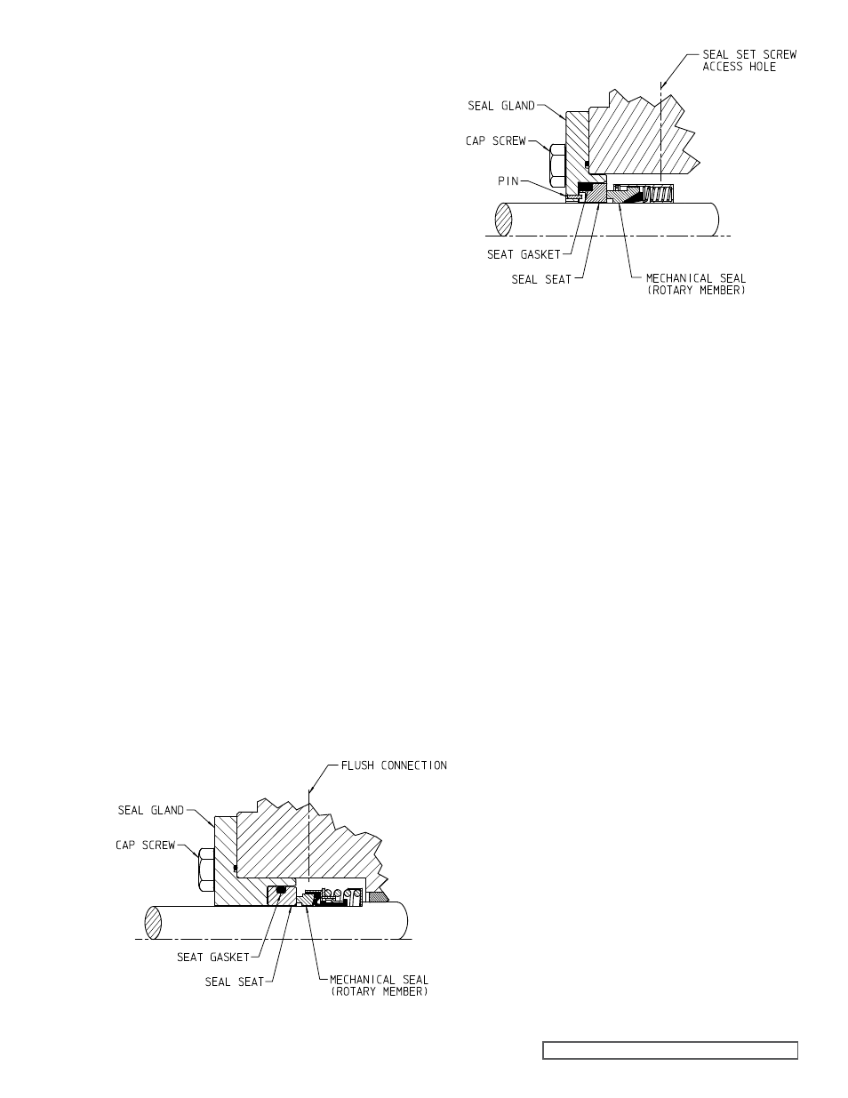
fIgURE 13
Elastomeric Bellows Seal
fIgURE 14
PTfE Wedge Seal
For complete pump assembly instructions, see
“Assembly,”
page 7.
1. Clean
the rotor shaft and seal housing bore. Make sure
they are free of dirt, grit and scratches. Gently radius the
leading edge of the shaft diameter over which the seal is
to be placed.
NOTE: Never touch the mechanical seal faces with
anything except clean hands or a clean cloth. Minute
particles can scratch the seal faces and cause leakage.
2. Coat
the shaft and the inside of the rotary member of
the seal with a generous quantity of light oil. Grease is
not recommended.
3. Start
the rotary member on the shaft (including the seat
collar and screws on the bellows seal) and ease over the
shaft.
NOTE: Some PTFE wedge seals are equipped with
holding clips, which compress the seal springs. Remove
the holding clips to release the springs after the seal is
installed on the shaft.
4. For PTFE wedge seal, move the rotary member so
the setscrews are directly below the seal access holes
on the side of the bracket (See
figure 14). Tighten all
setscrews securely to the shaft.
5. FOR “O-RING” GASKET TYPE MECHANICAL SEAL
SEAT (BELLOWS SEAL): Lubricate the outer diameter
of the O-ring seal gasket with oil. Flush the sealing faces
of both rotary member and seal seat with oil and press
the seal seat in to the bore until the back, unlapped face,
is flush with the bore. Install the seal holder, seal plate,
capscrews, and nuts and tighten securely.
FOR “CLAMPED-IN” TYPE MECHANICAL SEAL SEAT
(WEDGE SEAT): Flush the sealing faces of both the
rotary member and seal seat with oil and install the seal
seat and seal gasket over the end of the shaft against
the machined bracket face. Install the other seal gasket,
seal holder, seal plate, capscrews and nuts and fasten
securely.
NOTE: For component seals, LVP pumps come standard
with an internal suction lubrication line.
To complete assembly, refer to
“Assembly,” page 7.
Elastomeric Bellows and PTfE Wedge Type :
INSTALLATION Of BUSHINgS
When installing the silicon carbide or carbon graphite
bushings, extreme care must be taken to prevent breaking.
Carbon graphite is a brittle material and easily cracked. If
cracked, the bushing will quickly disintegrate. Using a lubricant
and adding a chamfer on the bushing and the mating part will
help in installation. The additional precautions listed below
must be followed for proper installation.
1. A press must be used for installation.
2. Be certain the bushing is started straight.
3. Do not stop pressing operation until the bushing is in
the proper position. Starting and stopping will result in a
cracked bushing.
4. Check
the bushing for cracks after installation.
LVP bushings with interference fits must be installed by a
shrink fit.
1. Heat
the casing or head to 750ºF.
2. Install
the cool bushing with a press.
3. If facilities are not available to reach 750ºF. temperature,
it is possible to install with 450ºF. temperature; however
the lower the temperature the greater the possibility of
cracking the bushing.
Consult factory with specific questions on high temperature
applications.
Refer to Engineering Service Bulletin ESB-3.