Disassembly – Viking Pump TSM445: LVP Vane Pumps User Manual
Page 5
SECTION TSM 445
ISSUE
C
PAGE 5 OF 11
1. Mark the head and casing before disassembly to ensure
proper reassembly.
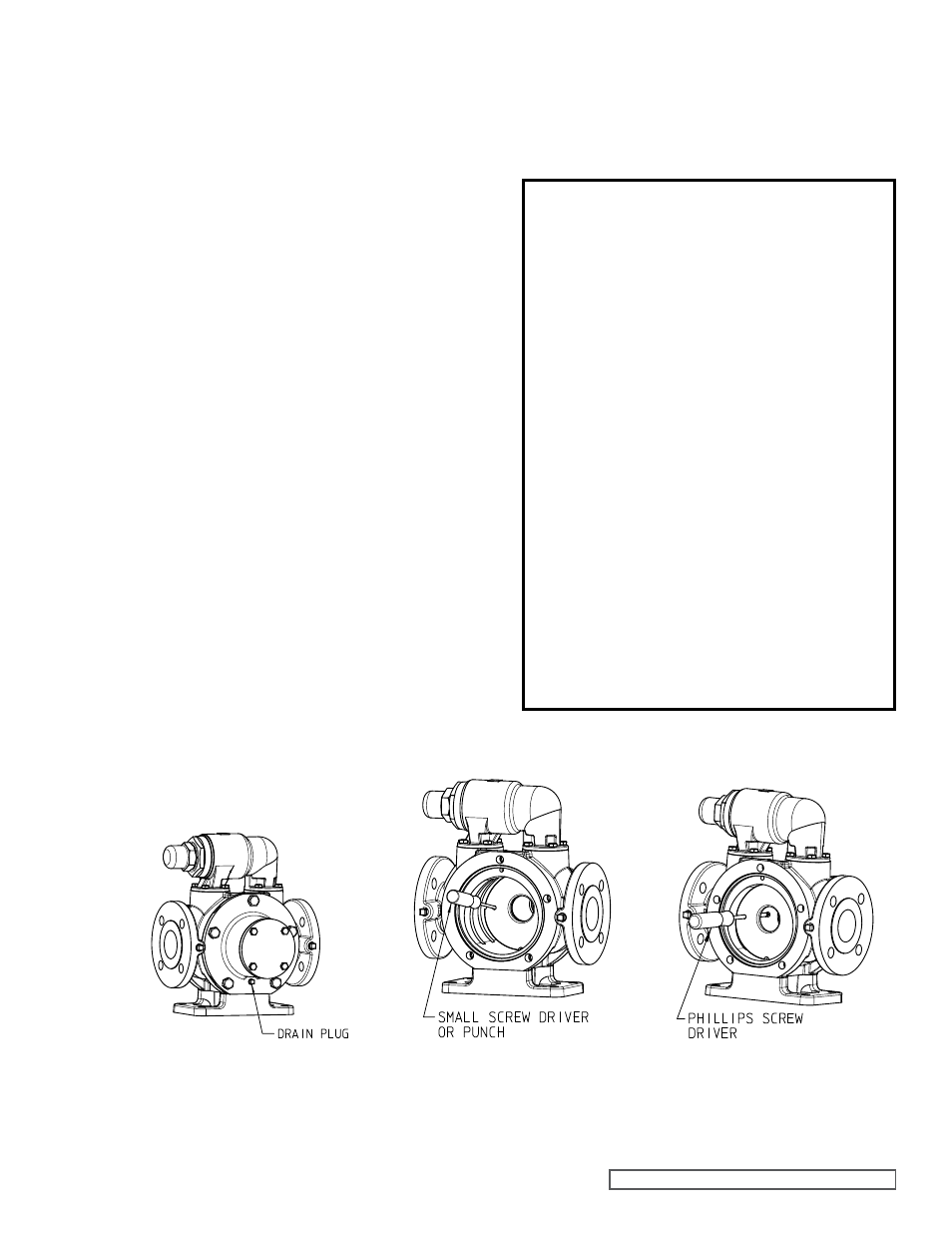
2. Relieve pressure and drain fluid by removing the drain
plug as shown in
figure 4.
3. Remove the head from the pump. If the pump is
furnished with a pressure relief valve, it need not be
removed from casing or disassembled at this point. Refer
to
“Pressure Relief Valve Instruction,” page 10.
4. Remove
the first carbon disc using caution not to break.
See
figure 5.
5. Remove the top vane from the rotor. Ensure the
pushrod is not obstructing the vane being removed.
Rotate the shaft and remove the other vanes in the same
manner.
6. Remove the seal gland capscrews, slide packing gland
out of the seal box, and remove the seal.
7. Loosen the mechanical seal setscrews for applicable
seals.
8. Ensure the pushrods are not lodged in ports prior to
removing the rotor.
NOTE: When disassembling a pump with a cartridge seal,
reference cartridge seal replacement beginning on page 8.
9. Carefully remove the rotor and shaft to avoid damaging
the bracket bushing. One or more pushrods may fall out
of the rotor upon removal from the casing. Take care
to not jam the pushrods between the casing and rotor
during the rotor removal.
10. Carefully remove the second carbon disc from the
casing. If the casing disc is jammed, a small screwdriver
or punch may be used as shown in
figure 5. Use the
screwdriver to help guide the disc out of the casing cam
bore as shown in
figure 6.
11. Press the bushings out of the casing and head if
replacement is needed. For the head bushing, remove
the head cover plate before pressing out the bushing.
DISASSEMBLY
DANgER !
Before opening any Viking pump liquid
chamber (pumping chamber, reservoir,
relief valve adjusting cap fitting, etc.)
Be sure:
1. That any pressure in the chamber has
been completely vented through the
suction or discharge lines or other
appropriate openings or connections.
2. That the driving means (motor,
turbine, engine, etc.) has been “locked
out” or made non-operational so that
it cannot be started while work is
being done on pump.
3. That you know what liquid the
pump has been handling and the
precautions necessary to safely
handle the liquid. Obtain a material
safety data sheet (MSDS) for the
liquid to be sure these precautions
are understood.
failure to follow above listed
precautionary measures may result in
serious injury or death.
12. Clean all parts thoroughly and examine for wear and
damage. Check the bushings, carbon discs, vanes,
pushrods and replace if necessary. Check all other
parts for nicks, burrs, excessive wear and replace if
necessary.
fIgURE 4
Location of drain plug.
fIgURE 5
Removal of Disc.
fIgURE 6
Use screwdriver to guide disc out.