Seal removal seal installation, Mechanical seal replacement – Viking Pump TSM445: LVP Vane Pumps User Manual
Page 8
SECTION TSM 445
ISSUE
C
PAGE 8 OF 11
DANgER !
Before opening any Viking pump liquid
chamber (pumping chamber, reservoir,
relief valve adjusting cap fitting, etc.)
Be sure:
1. That any pressure in the chamber has
been completely vented through the
suction or discharge lines or other
appropriate openings or connections.
2. That the driving means (motor,
turbine, engine, etc.) has been “locked
out” or made non-operational so that
it cannot be started while work is
being done on pump.
3. That you know what liquid the
pump has been handling and the
precautions necessary to safely
handle the liquid. Obtain a material
safety data sheet (MSDS) for the
liquid to be sure these precautions
are understood.
failure to follow above listed
precautionary measures may result in
serious injury or death.
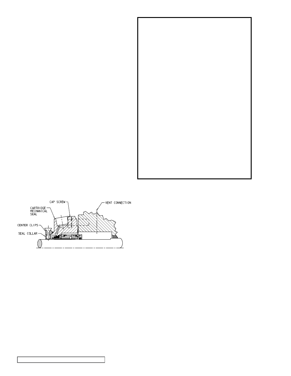
fIgURE 12
Cartridge Mechanical Seal
SEAL REMOVAL
SEAL INSTALLATION
Cartridge Type :
This manual provides instructions for the three standard
types of mechanical seals supplied on the following LVP vane
pump models:
LVP40017U, LVP40027U, LVP41057U, LVP41087U,
LVP41197U, LVP41237U, LVP41017U, LVP41027U,
LVP40017M, LVP40027M, LVP41057M, LVP41087M,
LVP41197M, LVP41237M, LVP41017M, LVP41027M
1. Cartridge
(figure 12)
2. Elastomeric Bellows Type 52, 8-1 (figure 13)
3. PTFE Wedge Type 9 (figure 14)
Identification of the seal type is an important step towards
proper maintenance. For mechanical seal types not shown,
see the Seal Instruction Drawing (SID) furnished with the
pump or contact a Viking representative.
Cartridge mechanical seals are designed so that they may be
replaced with minimal pump and piping disassembly.
1. Remove any flush or barrier fluid tubes connected to the
seal gland.
2. Loosen the setscrews on the seal collar to free the
cartridge seal from the shaft.
3. Remove the gland capscrews and slide the cartridge
seal off the end of the shaft.
If the pump is to be disassembled further, refer to
“Disassembly,” page 5.
Elastomeric bellows and PTFE wedge seals generally
require pump disassembly to be replaced (See
“Disassembly,” page 5).
1. Loosen the nuts and remove the seal gland plate, seal
plate holder, seal seat and seal gasket.
2. Loosen the setscrew in the set collar (bellows) or
mechanical seal rotary member (wedge).
NOTE: Piping
and/or plugs will need to be removed to access the
setscrews.
3. To complete the removal of the mechanical seal refer to
Step 6 of
“Disassembly,” page 5.
NOTE: Burrs left on the shaft can damage the O-ring on the
seal sleeve during installation. Inspect the shaft for burrs and
remove with a fine grade of emery cloth.
1. Clean
the shaft and the face of the seal chamber.
2. Coat the shaft and O-ring in the inside diameter of the
cartridge seal sleeve with a generous amount of light oil.
Refer to
figure 12.
3. Slide
the cartridge seal on the shaft until it contacts the
seal chamber face.
4. Insert
the gland capscrews and secure the gland to the
bracket face.
NOTE: Turn the shaft several turns while
the gland is loose to center seal; then tighten gland tight
enough to compress the gasket. Tighten only enough to
contain leakage and not to distort the gland.
5. Lock the cartridge seal drive collar to the shaft and
remove or turn the centering clips out of the way so as to
clear the drive collar.
6. Turn
the shaft by hand or jog the motor to check the
drive collar for runout.
7. Connect
the flush line or vent the stuffing box for seals
without the flush line until liquid is present on start up.
NOTE: For maximum seal life, the flush line should be
used.
MECHANICAL SEAL REPLACEMENT
Cartridge Type :
Elastomeric Bellows and PTfE Wedge Type :