Viking Pump TSM275: AL-05 User Manual
Page 9
Page 9
3.0 General
The pumping action of the rotary lobe pump principle is generated by the contra-
rotation of two pumping elements (rotors) within a chamber (rotorcase). The rotors
are located on shafts, which in turn are held within the pump body. The shaft
assemblies comprise of the support bearings and the timing gears. The timing gears
transfer the drive from the driven shaft to the lay shaft, synchronising the rotors such
that they rotate without contact with each other.
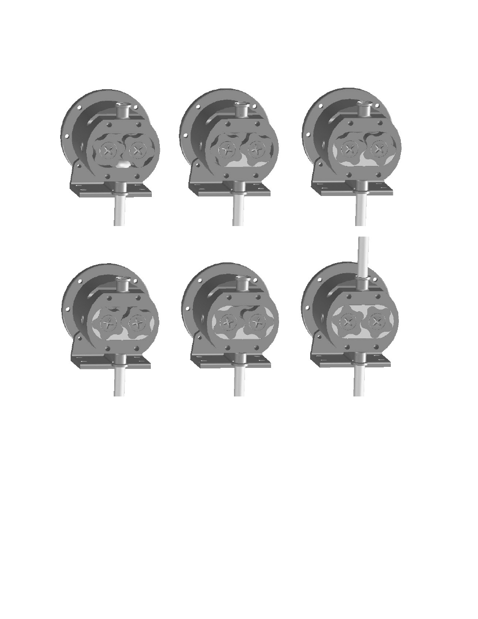
As the rotors pass the suction port, (see ‘A’), the cavity generated increases creating
a pressure decrease, which induces the media to be pumped to flow into the
rotorcase (‘B’).
The pumped media is carried around the rotorcase by the rotors; (‘C’ and ‘D’) to the
discharge side of the pump (‘E’). Here the cavity decreases and the pumped medium
is discharged from the rotorcase (‘F’).
The maximum pressure and speed operating parameters are shown below. In
practice these may be limited due to the nature of the product to be pumped and/or
F
E
D
C
B
A