The bearing housing assembly, Warning, Danger – Viking Pump TSM270.1: RL 16 and 25 Standard User Manual
Page 8
SECTION TSM
270.1
ISSUE
A
PAGE 8 OF 12
SECTION TSM
270.1
ISSUE
A
PAGE 9 OF 12
THE BEARING HOUSING ASSEMBLY
DISASSEMBLY
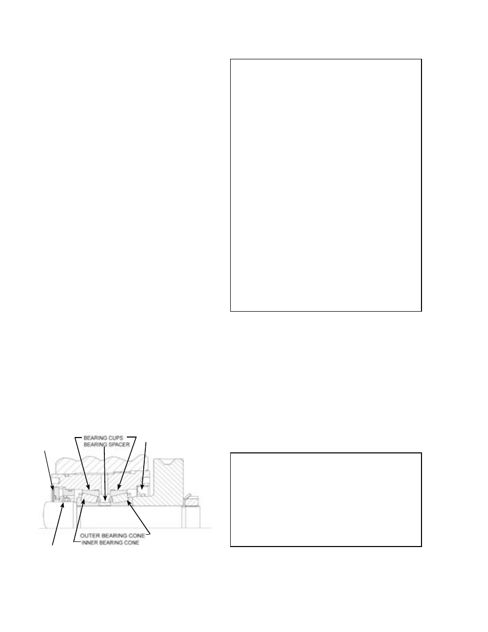
1. Remove the retaining ring. See Figure 8.
2.Remove the labyrinth seal and lipseal, and replace if
needed.
CAUTION: The tapered roller bearings and spacers are
supplied as matched sets. Do not mix with cups, cones or
spacers from other sets.
ASSEMBLY
CAUTION: If the tapered roller bearings are not being
replaced, be sure to keep each cup with its respective cone,
because they track to each other during operation.
1. Press both bearing cups into the bearing housing.
2. Install the matching bearing cone closest to the labyrinth
seal first. Apply a lubricant to the ID and into the groove
on the face of the labyrinth seal and install. Install the
retaining ring.
3. On the opposite side, install the spacer, remaining
bearing cone and press in the lipseal.
FIGURE 8
1. Remove the pump head if it is not already off.
2. Remove the pipe plugs (item 29) from the bracket and
loosen the setscrews (item 28) on the bearing housing.
3. Using the pin-style spanner wrench, turn the bearing
housing counter clockwise (as viewed from shaft end),
until the lobe is touching the bottom of the casing bore.
4. Using a depth micrometer, measure the depth from the
front face of the casing to the face of the lobe; this is the
total end clearance.
5. Multiply total end clearance by 0.6. Turn the bearing
housing clockwise until the lobe is this distance from the
front face of the casing.
WARNING:
The end clearance must be set while turning the
bearing housing assembly clockwise. If it is set
while turning counter-clockwise, the lobes may float
and cause damage or galling.
Recheck to make sure locknuts are tight. If left
loose, the end clearance may be lost, resulting in
pump seizure.
DANGER !
Before opening any Viking pump liquid chamber
(pumping chamber, reservoir, etc.) be sure:
1. That any pressure in the chamber has been
completely vented through the suction or
discharge lines or other appropriate openings or
connections.
2. That the driving means (motor, turbine, engine, etc.)
has been “locked out” or made non-operational so
that it cannot be started while work is being done
on pump.
3. That you know what liquid the pump has been
handling and the precautions necessary to
safely handle the liquid. Obtain a material safety
data sheet (MSDS) for the liquid to be sure these
precautions are understood.
4. That
the timing gearbox to cool before handling
the pump. The oil will become very hot during
normal operation. Allow the timing gearbox oil.
Failure to follow above listed precautionary mea-
sures may result in serious injury or death.
END CLEARANCE ADJUSTMENT
3. The matched bearing set consists of two cups, two
cones and a spacer. Remove the inner bearing cone
and spacer and inspect for wear. Also inspect the inner
bearing cup for wear. Do not remove the bearing cups
unless they are to be replaced, as they are pressed in.
Inspection of the outer bearing will be difficult since the
outer bearing cone cannot be removed with the lip seal
installed. To remove outer bearing cone, remove the lip
seal, which will need to be replace with a new one for
assembly. Inspect the outer cup and cone for wear. If
any part of the bearing needs to be replaced, replace all
five parts as a match set.
LABYRINTH SEAL
6. Evenly tighten the bearing housing setscrews on both
sides of the bracket and reinstall the pipe plugs.
7. Repeat this procedure for the other lobe.
RETAINING
RING
LIPSEAL
TIMING
GEAR