Pump disassembly, Warning, Danger – Viking Pump TSM270.1: RL 16 and 25 Standard User Manual
Page 7
SECTION TSM
270.1
ISSUE
A
PAGE 6 OF 12
SECTION TSM
270.1
ISSUE
A
PAGE 7 OF 12
WARNING:
Do not use the circulation tubing to lift the pump or
casing. Make sure the casing is secured to a work
bench or other stable work surface before working
on the pump.
PUMP DISASSEMBLY
DANGER !
Before opening any Viking pump liquid chamber
(pumping chamber, reservoir, etc.) be sure:
1. That any pressure in the chamber has been
completely vented through the suction or
discharge lines or other appropriate openings or
connections.
2. That the driving means (motor, turbine, engine, etc.)
has been “locked out” or made non-operational so
that it cannot be started while work is being done
on pump.
3. That you know what liquid the pump has been
handling and the precautions necessary to
safely handle the liquid. Obtain a material safety
data sheet (MSDS) for the liquid to be sure these
precautions are understood.
4. That
the timing gearbox to cool before handling
the pump. The oil will become very hot during
normal operation. Allow the timing gearbox oil.
Failure to follow above listed precautionary mea-
sures may result in serious injury or death.
1.Remove the cover plate capscrews and remove the
cover plate from the bracket.
2. Loosen the capscrews on the seal gland and the
setscrews that hold the seal on the shaft sleeve.
NOTE: The loosening of the seal setscrews and gland
capscrews should always be the first step whenever working
on the pump.
3. Drain the oil from the timing gear case by removing
the pipe plug (item 1). Remove the capscrews, then
carefully slide the gear case cover off the driver shaft.
4. Remove the capscrews and head.
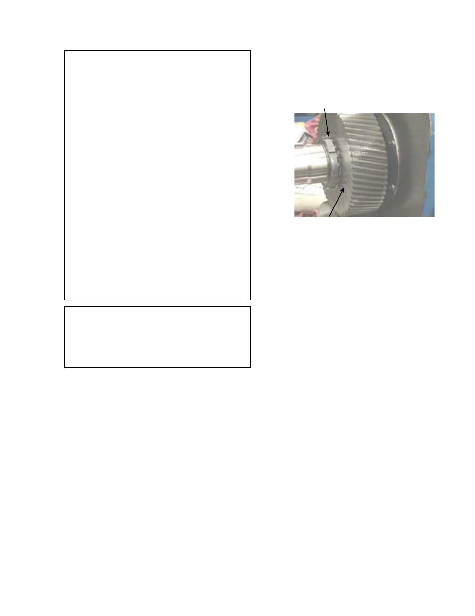
5. Straighten out the bearing lockwasher tab on both shafts
(see figure 7). Place a wooden block or brass bar in
between the lobes to block rotation of the shafts. Use
the spanner wrench (Suggested Repair Tools # 5) to
remove the locknut. Remove the wooden block and
insert on the opposite side to restrict movement of the
other shaft. Remove the second locknut. Remove both
of the lockwashers.
6. Slide the timing gears off the shafts. If the timing gears
do not come off easily, use jackscrews (Suggested
Repair Tools # 6) (figure 7).
Bearing Lockwasher Tabs
3/8” Jackscrew Holes
FIGURE 7
7. Loosen the setscrews (item 28) in the bracket that
secures the bearing housings.
8. Remove the Bearing Housing Assemblies using the
spanner wrench (Suggested Repair Tools # 4). For
complete Bearing Housing Disassembly, see page 8.
9.Remove the capscrews (item 32) and the bracket.
10.Remove the four capscrews and washers that hold
each cartridge mechanical seal in place and remove
the seals. Refer to figure 4. For other optional sealing
instructions refer to Mechanical Seal Information on
pages 5 and 6.
11.Remove the lobe/shaft assemblies.
12.Remove the snap rings to pull the shafts from the lobes.