Optional packing replacement only, Labyrinth seal, Optional cartridge lipseal seal replacement only – Viking Pump TSM270.1: RL 16 and 25 Standard User Manual
Page 6
SECTION TSM
270.1
ISSUE
A
PAGE 6 OF 12
SECTION TSM
270.1
ISSUE
A
PAGE 7 OF 12
Optional Packing Replacement Only
REMOVAL
1. Remove the packing gland capscrews.
2. If the pump bracket is still assembled, there is enough
room to slide the packing gland back and pull out
the packing with a packing hook, without further
disassembly.
INSTALLATION
1. Clean the stuffing box thoroughly and check the shaft for
smoothness. Scored shafts should be replaced.
2. Lubricate the packing rings with an appropriate
lubricant. Install and seat each ring of packing one at a
time, staggering the ring joints 90° apart. Push each ring
in by hand using the packing gland or by tightening two
opposite packing gland capscrews.
3. Install the packing gland washers and capscrews.
Tighten the packing gland until it becomes snug. Do not
over-tighten.
4. On start-up of the pump, carefully tighten the gland
to reduce leakage until a desired leakage rate is
obtained. Excess leakage during the break-in period
is necessary to help lubricate and cool the packing. A
maximum adjustment of approximately 1/8 turn at a time
is recommended. If during this period heating occurs,
back off the gland and allow to run until stuffing box
cools. Then, begin readjustment.
NOTE: Some leakage is required for packing lubrication.
The amount will vary depending on the application. Consult
your authorized Viking representative for more information.
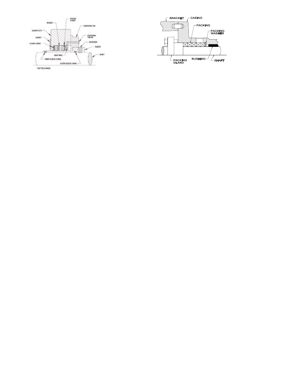
Labyrinth Seal
All labyrinth seals contain 4 common parts:
Stationary Element
Stationary O-ring
Rotating Element
Rotating O-ring
It is recommended to replace any O-rings that are removed
from their initial seat. It is recommended to replace the
entire seal if the stationary and rotating elements become
separated.
FIGURE 6
REMOVAL
1.Remove the cover plate capscrews and remove the
cover plate from the bracket.
2.Loosen the seal setscrews and remove the seal gland
capscrews and washers.
3.Remove the head capscrews and head.
4.Remove the lobe snap rings, lobes and keys.
5.Remove the capscrews connecting the bracket to the
casing, and pull the casing from the bracket.
6.Remove the seals.
INSTALLATION
1.Lubricate the seal ID and pump shaft with an
appropriate lubricant. Slide each seal onto a
shaft, and place 5.25” past the step on the shaft.
2.Replace the casing, being careful not to damage the
bushings on the steps of the shafts, and secure to the
bracket with capscrews.
3.Install the keys and lobes, and secure with the snap
rings. The flat side of the snap ring should face the lobe.
4.Install the O-ring, head and capscrews.
5.Slide the seals towards the casing until the glands contact
the stuffing box face. Turn the centering tabs inward.
6.Secure the seal glands to the casing with washers and
capscrews. Torque the bracket, head and finally the
seal gland capscrews according to Table 2 on page 3.
7.Tighten the seal setscrews and turn the centering tabs
outward.
8.Replace the cover plate and capscrews on the bracket.
FIGURE 5
NOTE: Good radial alignment is required for proper
operation of the seals. This is accomplished by the use of
centering tabs provided with each seal. Turn the tabs inward
when installing or removing the seal. Turn them outward for
normal operation of the pump.
Optional Cartridge Lipseal Seal Replacement
Only