Mechanical seal information, Danger, Cartridge mechanical seal replacement only – Viking Pump TSM270.1: RL 16 and 25 Standard User Manual
Page 5: Warning
SECTION TSM
270.1
ISSUE
A
PAGE 4 OF 12
SECTION TSM
270.1
ISSUE
A
PAGE 5 OF 12
The Industrial Lobe series pump can be supplied with a
variety of mechanical sealing configurations and materials.
A cartridge mechanical seal is considered standard
construction.
Complete pump disassembly is not necessary if only the
cartridge seals are being replaced. For seal replacement
only, access to the seals from the head end of the pump is
more efficient.
General installation and replacement instructions for the
sealing options are provided. It is also recommended to
review the seal manufacture’s instructions.
For complete pump disassembly and assembly instructions
see pages 7 through 9.
MECHANICAL SEAL INFORMATION
DANGER!
Before starting pump, be sure all drive equipment
guards are in place.
Failure to properly mount guards may result in seri-
ous injury or death.
DANGER !
Before opening any Viking pump liquid chamber
(pumping chamber, reservoir, etc.) be sure:
1. That any pressure in the chamber has been
completely vented through the suction or
discharge lines or other appropriate openings or
connections.
2. That the driving means (motor, turbine, engine, etc.)
has been “locked out” or made non-operational so
that it cannot be started while work is being done
on pump.
3. That you know what liquid the pump has been
handling and the precautions necessary to
safely handle the liquid. Obtain a material safety
data sheet (MSDS) for the liquid to be sure these
precautions are understood.
4. That
the timing gearbox to cool before handling
the pump. The oil will become very hot during
normal operation. Allow the timing gearbox oil.
Failure to follow above listed precautionary mea-
sures may result in serious injury or death.
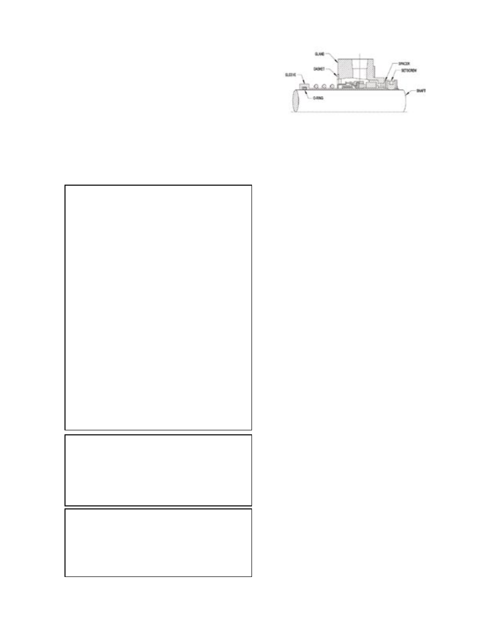
FIGURE 4
Cartridge Mechanical Seal Replacement
Only
REMOVAL
1.Remove the cover plate capscrews and remove the
cover plate from the bracket.
2.Loosen the seal setscrews and remove the seal gland
capscrews and washers.
3.Remove the head capscrews and head.
4.Remove the lobe snap rings, lobes and keys.
5.Remove the capscrews connecting the bracket to the
casing, and pull the casing from the bracket.
6.Remove the seals.
INSTALLATION
1.Lubricate the seal ID and pump shaft with an appropriate
lubricant. Slide each seal onto a shaft, and place about
5.25” past the step on the shaft.
2.Replace the casing, being careful not to damage the
bushings on the steps of the shafts, and secure to the
bracket with capscrews.
3.Install the keys and lobes, and secure with the snap rings.
The flat side of the snap ring should face the lobe.
4.Install the O-ring, head and capscrews.
5.Slide the seals towards the casing until the glands
contact the stuffing box face.
6.Secure the seal glands to the casing with washers and
capscrews. Torque the bracket, head and finally the seal
gland capscrews according to Table 2 on page 3.
7.Tighten the seal setscrews.
For optional cartridge mechanical seals that have setting
clips, remove them.
8.Replace the cover plate and capscrews on the bracket.
WARNING:
Do not use the circulation tubing to lift the pump or
casing. Make sure the bracket is secured to a work
bench or other stable work surface before working
on the pump.