Labyrinth seal, Assembly, The bearing housing assembly – Viking Pump TSM270: RL41507 Industrial Rotary Lobe User Manual
Page 7
SECTION TSM
270
ISSUE
F
PAGE 7 OF 10
THE BEARING HOUSING ASSEMBLY
LABYRINTH SEAL
All labyrinth seals contain 4 common parts:
Stationary Element
Stationary O-ring
Rotating Element
Rotating O-ring
It is recommended to replace any O-rings that are removed
from their initial seat. It is recommended to replace the
entire seal if the stationary and rotating elements become
separated.
ASSEMBLY
1.If the casing or head bushings are worn or grooved,
install new bushings. Refer to INSTALLATION OF PEEK
BUSHINGS, page 9. Head bushings are not generally
field replaceable. If these bushings are worn or grooved,
consult the factory or you local distributor.
Caution: The lobe and shaft assembly weighs 130
pounds and will require 2 people to install, or the use of
an overhead hoist.
2.Coat the bottom casing bushing bore with light oil then
gently slide the driven shaft (shorter shaft) in place. Hold
the shaft as horizontal as possible when installing. This
helps avoid damaging the bushing when the step on the
shaft slides into the bushing bore. Slide the lobe all the
way into the casing bore and position the lobe as shown
in Figure 9. Repeat this process with the driver shaft,
being careful not to damage the bushing on the shaft’s
multiple steps. Slide lobe completely into casing.
3.Position the casing so the bracket can be installed
without bearing any load. Refer to figure 8. A lifting strap
connected to overhead support will assist in attaching
the bracket to the casing. Secure the bracket with the
(8) nuts.
4.Remove the pump head. Refer now to Figure 10. The
bearing housing should already have the inner lip seal
and labyrinth seal installed. Press the inner spacer
(Item # 22) into the labyrinth seal and lip seal. Install O-
rings (Item #19) onto the bearing housings. Thread the
bearing housing into the bracket and temporarily install
all six 5/16” capscrews to assist in getting the housing
threads started. Repeat for the upper bearing housing.
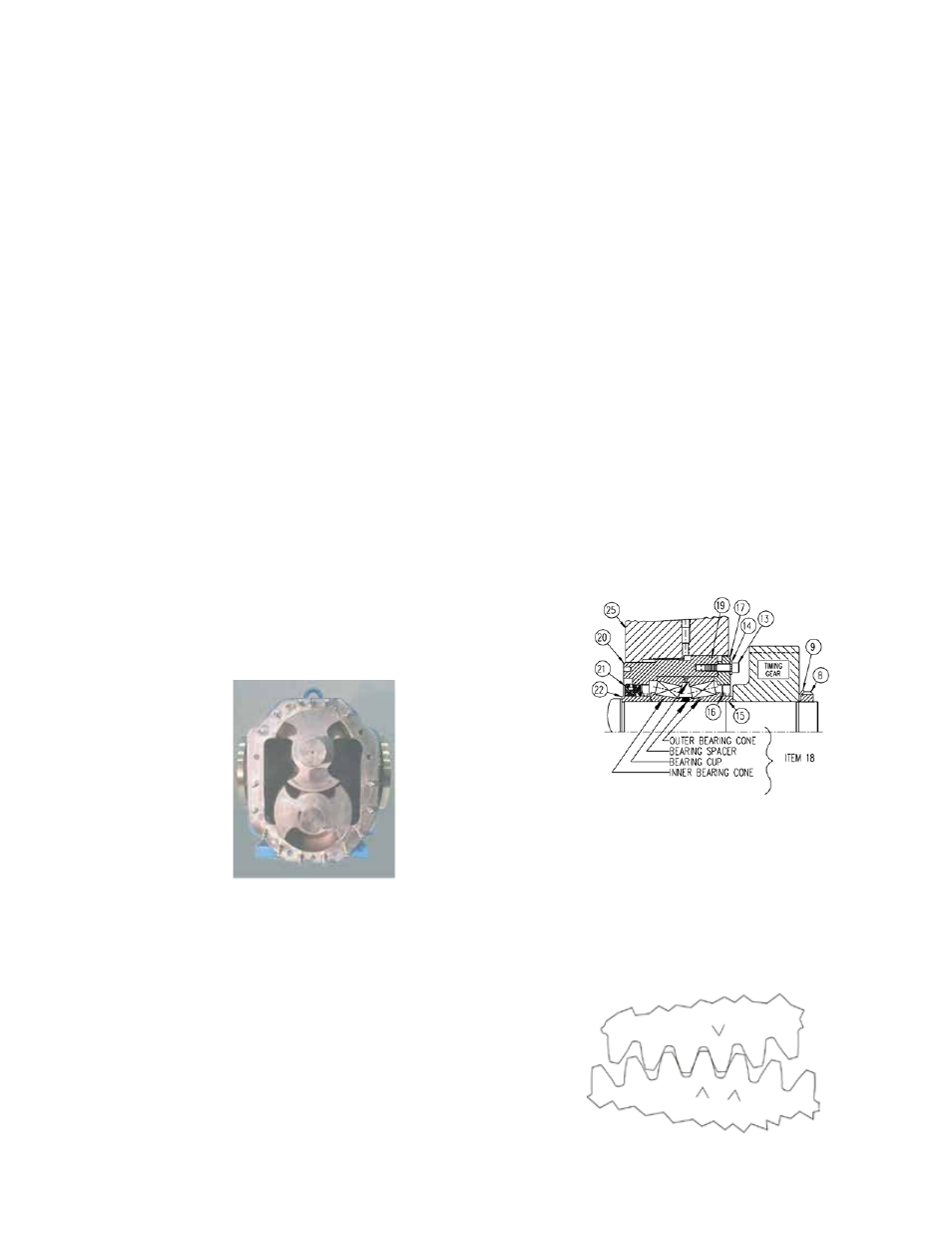
FIGURE 11
5.Apply a liberal coating of anti-seize and lubricating
compound (such as NEVER-SEEZ BY BOSTIK) to the
shafts and threads. Install the inner bearing cone, cup,
spacer (3/8” width), and outer bearing cone. Repeat
for the other shaft. Install the bearing endcap. The
endcap should have the outer spacer and lipseal already
installed. Torque capscrews (Item # 13) evenly to 18 ft-lb
torque.
6.Add a light film of oil onto the end of the shaft prior to
installing the head. This is a temporary installation so
you will not need the O-ring in place. Thread in some ¾”
bolts into the back side of the head to help position the
head. Line up the head bushing bores with the ends of
the two shafts and slide onto the shafts, studs and finally
the dowel pins. The head may require lifting slightly to
get onto the dowel pins. Place four nuts, one in each
corner, onto the head studs to keep the head in place
and thread on finger tight.
Caution: Make sure the head is positioned properly
over the locating pins before tightening bolts to avoid
damaging the bushings. It may be necessary to tap the
head with a soft hammer.
7.Install the two P/S
®
-II seals next, starting with the bottom
shaft. Coat the shafts and ID of the seals with light oil
to facilitate installation. Make sure there are no nicks on
the shaft from previous usage. Secure each seal with (4)
5/8” capscrews, lock washers and flat washers (items
#30, 43 & 44) and tighten to 15 ft-lb torque.
8.Apply a liberal coating of anti-seize or lubricating
compound on the area of the shaft underneath the
timing gear. Insert keys into shafts. Install the timing
gears, positioned as shown in Figure 11, with arrows
meshed. Rotate the driver shaft by hand, to be sure
the timing gears are properly aligned. If not, check the
arrows again to make sure they are positioned as shown
in Figure 11.
FIGURE 9
FIGURE 10