Cartridge seals, The bearing housing assembly – Viking Pump TSM270: RL41507 Industrial Rotary Lobe User Manual
Page 6
SECTION TSM
270
ISSUE
F
PAGE 6 OF 10
9.Remove the outer cone of the tapered roller bearing. It
might be necessary to thread the bearing housing back
into the bracket. Remove the spacer between the two
cones and the cup of the bearing set.
CAUTION: It is important to keep the bearing together as
a set and in the proper order since the spacer is ground
specifically for those components to provide the proper
preload.
THE BEARING HOUSING ASSEMBLY
10.Remove the inner bearing cone, if it doesn’t slide freely,
reinstall the end cap and capscrews and use a puller
(see figures 6 and 10). The back side of the end cap has
a machined recess to allow puller usage. Slide the inner
spacer (Item #22) off shaft. Repeat the process for the
other bearing housing.
11.Reposition the pump so the bracket is free standing. See
figure 7. Place a lifting strap through the top bearing
bore and support from overhead. Remove the (8) ½”
nuts (Item #26) then remove the bracket. Pull the
bracket off of the dowel pin and studs.
12.Depending on the type of mechanical seal used, make
sure the securing devices to hold or stabilize the
seal while removing from the shaft are in place and
positioned properly. Unlock the setscrews securing the
sleeve to the shaft. Remove the (4) capscrews that hold
each seal in place then pull the seal off the shaft.
13.The lobe and shaft assembly is now ready to pull out of
the casing.
Caution: This assembly weighs 130 pounds and requires
two people or an overhead hoist to handle.
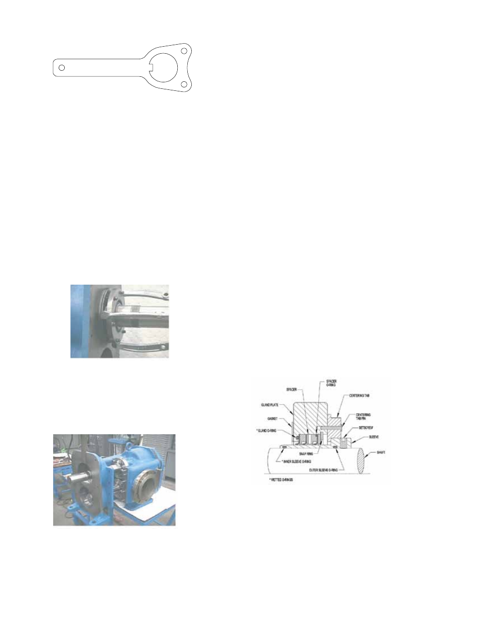
CARTRIDGE SEALS
The standard seals used in this pump are Fluidtec P/S
®
-II
(Figure 8) and are simple to install. Proper care on installation
will help in providing good service life.
Good radial alignment is required for proper operation
of the seals. This is accomplished by use of centering
tabs provided with each seal. Turn the tabs inward when
installing or removing the seal. Turn them outward for
normal operation of the pump.
14.Slide the driver shaft out 10” and have one person
support the assembly. Continue sliding the assembly
out with the other person supporting the opposite end of
the shaft. Repeat these steps for the driven shaft.
15.Inspect the labyrinth seals (Item #21) and lip seals in
each bearing housing. Leave in the housing unless
they show signs of wear or damage (See LABYRINTH
SEAL, page 7).
16.Clean all parts thoroughly and examine for wear or
damage. Check the lip seals, bearings, bushings and
replace if necessary. Check all other parts for nicks,
burrs or excessive wear and replace if necessary.
Pay special attention to the shaft area underneath the
mechanical seal where seal set screws contact.
CAUTION: Do not mix the two bearing cones with
respect to the one piece cup.
17.Wash bearings in clean solvent and blow out with
compressed air. Make sure bearings are clean, then
lubricate with light oil. Check for roughness by placing
the cone on the cup and turning.
Bearing Housing Spanner Wrench
Part No. 2-810-060-375
FIGURE 5
FIGURE 6
FIGURE 7
FIGURE 8