Figure 23. four-wire intercom configuration, Figure 24. three-wire intercom configuration, Figure 25. two-wire intercom configuration – Unitec Portal Installation Manual User Manual
Page 33
P O R T A L T I
Portal Installation Manual Rev C
29
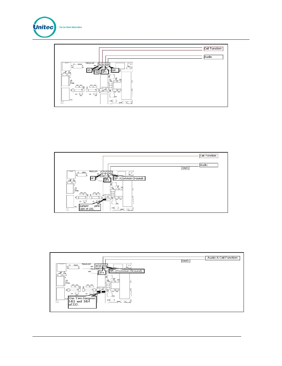
Figure 23. Four-Wire Intercom Configuration
3 Wire Intercom Configuration: This mode requires two conductors for audio and
one additional conductor for the call function. This mode uses a common ground for
both audio and the call function (SP-). Jumper pins 3&4 of J35 and connect H1, SP+
and SP- as shown below.
Figure 24. Three-Wire Intercom Configuration
2 Wire Intercom Configuration: This type of intercom system has both the Call
Function and audio sharing the two conductors. Jumper pins 3&4 and 1&2 of J35 and
connect the two conductors to SP+ & SP- as shown below.
Figure 25. Two-Wire Intercom Configuration
Document #: PTL1001