Connecting torch, Spare parts label, Torch parts selection – Tweco SL100 User Manual
Page 2
Manual 0-2880
2
NOTE
Power Supply characteristics will determine material
thickness range.
D. Torch Ratings
SL60 Torch Ratings
Ambient
Temperature
104° F
40° C
Duty Cycle
100% @ 60 Amps @ 400 scfh
Maximum Current
60 Amps
Voltage (Vpeak)
500V
Arc Striking Voltage
7kV
SL100 Torch Ratings
Ambient
Temperature
104° F
40° C
Duty Cycle
100% @ 100 Amps @ 400 scfh
Maximum Current
100 Amps
Voltage (Vpeak)
500V
Arc Striking Voltage
7kV
E. Type of Cooling
Combination of ambient air and gas stream through
torch.
F. Gas Requirements
SL60 and SL100 Torch Gas Specifications
Gas (Plasma and Secondary)
Compressed Air
Operating Pressure
Refer to NOTE
60 - 75 psi
4.1 - 5.2 bar
Maximum Input Pressure
125 psi / 8.6 bar
Gas Flow (Cutting and Gouging)
300 - 500 scfh
(142 - 235 lpm)
!
WARNING
This torch is not to be used with oxygen (O
2
).
NOTE
Operating pressure varies with torch model, operat-
ing amperage, and torch leads length. Refer to gas
pressure settings chart for each model.
G. Direct Contact Hazard
For exposed tip the recommended standoff is 1/8" - 1/4"
(3 - 6.4 mm).
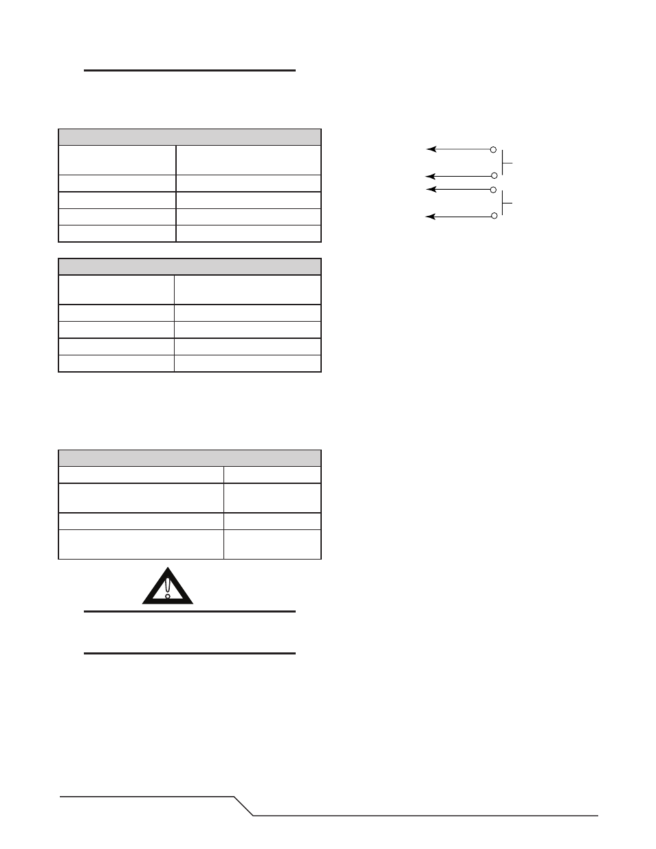
H. Parts-In-Place (PIP) Circuit - 12 vdc
The torch and leads include circuitry called Parts-
In-Place (PIP). This circuit includes a switch located
at the torch head. The shield cup closes this switch
when properly installed. The torch will not operate
if this switch is open.
A-02997
Torch Trigger
PIP Switch
Shield Cup
To Control
Cable Wiring
Torch Switch
Connecting Torch
There are two types of connection for the Torch Leads.
One type uses the Victor Thermal Dynamics ATC connec-
tor. The other uses O2B connections for gas and circuitry.
Both types require an adapter kit sold separately.
ATC Connectors
Follow the instructions provided with the adapter kit to
connect the adapter to the power supply.
Inspect the halves of the ATC Connector. Align the male
connector with the female receptacle and push them
together by hand until they seat fully. Turn the Locking
Ring until it pulls the halves of the connector together
fully. Do not use tools to tighten the connector. If there
is any resistance to the ring turning, pull the halves of the
connector apart, realign the inner components, ensure
that the threaded components are aligned, and push the
halves of the connector together again.
O2B Connectors
Leads with O2B connectors are connected to the power
supply using adapter kits sold separately. Follow the
instructions provided with the adapter kit to connect the
gas and electrical lines to the power supply.
Spare Parts Label
The parts kit provided with the torch includes an adhe-
sive label. Select the small perforated section showing
the appropriate pressure setting for the amperage output
and leads length to be used with this torch. Refer to the
charts. Apply this section in the 'Gas Supply' area of the
label under the 'Recommended Operating Pressure' text.
Discard any pressure setting sections of the label that will
not be used. Apply the large label to the power supply,
where the operator can see it for easy reference.
Torch Parts Selection
Refer to the Consumables Selection Chart for the various
torch parts for the application and operation.