Tweco 4-3054 User Manual
Page 3
Manual 0-4964 Rev AA.01
February 5, 2007
3
4. Once all connections have been made, a careful check
of all fi ttings for leaks and function needs to be made. Use
a standard leak detection or soap based liquid to test for
leaks. Turn the system on and check setting displays for
each of the gasses.
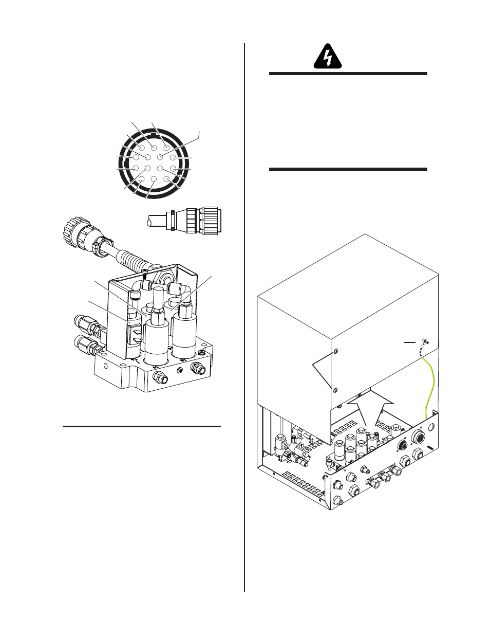
Control Connector Pinout Diagram
3: Ground
9: To SOL15 (Btm)
5: To SOL14 (Top)
4
1: To SOL16 (Top)
2: To SOL16 (Btm)
6: To SOL14 (Btm
7
10
13
14
11
12
8: To SOL15 (Top)
Art # A-07647
SOL15
SOL18
SOL16
SOL19
SOL14
& SOL18
& SOL18
& SOL19
& SOL19
Fuse Update on Main PCB in GCM 2010
NOTE
Depending on version at time of purchase
or other updates some GCM 2010 units may
not need to have the fuses updated. It will be
necessary to verify this. One way to do that is
by removing the cover and inspecting the two
fuses at F14 and F15. The following explains
how to do that and update the two fuses.
WARNINGS
Disconnect primary power at the source before
starting the procedure.
Use caution when handling the printed circuit
board as damage can result from improper
handling or from electrostatic discharge. Wear
appropriate static-handling equipment and
grounding strap while performing this replace-
ment procedure.
1. Remove the screws securing the cover panel to the gas
control module. Save the hardware for re-use.
2. Carefully remove the cover from the module noting
the attached ground wire. Remove the ground wire if
needed.
Art # A-06882
Gas Control Module Cover
Do not remove
Remove Ground
Wire
3. Locate the Main PCB mounted on the left side panel.
Remove the multi pin harness from the upper right at
J13.