Tweco 7-3360 User Manual
Page 3
August 19, 2005
3
Manual 0-2555
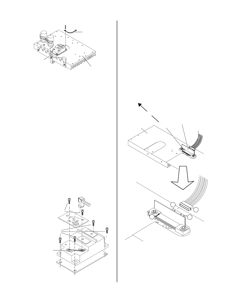
PTC Resistor
Assembly
Q1
Main Heatsink
Art # A-01089
PTC Resistor Assembly Location
7. Remove the four screws securing the Switching Tran-
sistor/IGBT module to the Main Heatsink. Be careful
not to damage the surface of the heatsink.
8. Pry between the Main Heatsink and the faulty Switch-
ing Transistor/IGBT Assembly until it slides easily.
9. Remove the faulty Switching Transistor/IGBT Assem-
bly from the unit by sliding it towards the center of the
Main Heatsink.
10. If the transistor thermal pad was not removed with the
transistor, remove it now.
11. Use isoproply alcohol to clean the residue of the old tran-
sistor thermal pad from the transistor mounting area.
12. Install the replacement Thermal pad, the IGBT Assem-
bly, IGBT Suppressor PC Board, and the replacement
wire harness included in this kit in the sequence
shown. Note the torque requirements. Connect the
other end of the harness to the terminal from which the
previous harness was disconnected, on the driver PC
board.
Art # A-06083
6. Connect Harness.
1. Install Thermal Pad.
5. Install IGBT
Suppressor
PC Board.
Torque hardware
to 14 in-lbs.
(1.6 N-m).
2. Install IGBT.
3. Remove
copper tape.
4. Torque IGBT
hardware (only)
to 26 in-lbs.
(2.9 N-m).
IGBT Installation Sequence
D. Shunt Amp PCB Replacement
1. Locate the Shunt Amp PCB, mounted to the Shunt on the
main heatsink.
2. Use the grounding wrist strap provided separately in
this kit. Follow all static handing instructions on the
separate instruction sheet.
3. Open two locking tabs securing the ribbon cable con-
nector to the Shunt Amp PCB. Carefully remove the
cable connector from the Shunt Amp PCB.
4. Loosen, but do not remove, the bolt securing the Shunt
to the main heatsink, to allow access to screws secur-
ing the Shunt Amp PCB to the Shunt.
Art # A-03839
Main Heatsink
Shunt
Shunt
Amp PCB
Ribbon
Cable
1
2
1
3
Rear of Power Supply
Shunt Amp PCB Disconnection