Tweco 7-3360 User Manual
Page 2
August 19, 2005
2
Manual 0-2555
B. Driver PC Board Assembly Installation
1. Locate the old Driver PC Board Assembly on the inside
left side, behind the front panel, as viewed from the
front of the unit.
Driver PC Board
Rear of Front Panel
A-01083
Driver PC Board Location
2. Note and label the two wiring connectors that connect
to the Driver PC Board.
3. Disconnect the two wiring connectors from the Driver
PC Board.
4. Press in the securing tab knob on the PC Board Guide
to release the PC Board from the PC Board Guides.
There is a securing tab on both the upper and lower PC
Board Guides.
Upper PC Board Guide
Lower PC Board
Guide
Securing Tab
Securing Tab
Driver PC
Board
A-01084
PC Board Guide Securing Tab
5. Carefully pull the PC Board from the guides and re-
move from the unit.
6. Install the replacement Driver PC Board Assembly re-
versing the above steps.
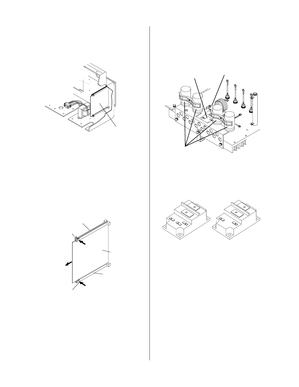
C. IGBT (Q1) Installation
1. Locate the old Switching Transistor/IGBT Assembly
on the inside center-left, between the four large blue
capacitors, as viewed from the front of the unit.
Switching Transistor
Q1
Large Blue
Capacitors
A-01085
Transistor/Coil
Bracket
2. There are two different types of Switching Transistor/
IGBT. The types can be identified by the top of the
transistor casing. This kit replaces both types.
Style With 2 Terminals
Style With 3 Terminals
Art # A-06055
Switching Transistor/IGBT Styles
3. Remove the two screws securing the wires to the Switch-
ing Transistor/IGBT Assembly terminals. Remove
and discard the wire harness.
4. Remove the screw that secures the Capacitor Mount-
ing Bracket to the Switching Transistor/IGBT Assem-
bly.
5. Remove the screw that secures the Transistor/Coil
Bracket to the Switching Transistor/IGBT Assembly.
6. Remove the screw and washer securing the PTC Resis-
tor Assembly to the Main Heatsink. Move the PTC
Resistor Assembly out of the way to prevent it from
becoming damaged.