Preparation, Fiber optic cable installation, Gas control module cover – Tweco 9-9435 User Manual
Page 2: Do not remove, 23 circuit board, Fiber optic cable
March 6, 2006
2
Manual 0-4738 Rev. AA
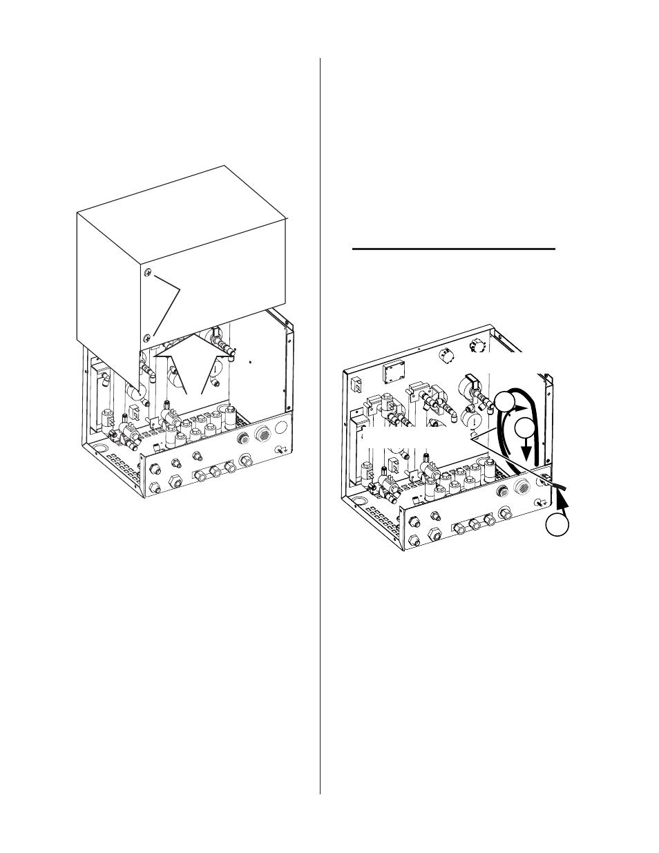
Preparation
1. Remove the screws securing the cover panel to
the Module.
2. Remove the Cover from the Module.
Art # A-07287
COM
M
J57
J56
INPUTS
TVA
PO
WER
SUPPL
Y
H35
AIR
N
2
O
2
Gas Control Module Cover
SHIE
LD
PLA
SMA
PRE
FLO
W
H2O
SHIELD
H2O
Do not remove
Fiber Optic Cable Installation
1. Remove the securing nut from the through-hole
protector supplied on the cable. Pass the cable
and the through-hole protector into the hole in
the connection panel on the back of the mod-
ule. Fasten the through-hole protector in place
with the securing nut. Do not tighten the pro-
tector.
2. Pass the fiber-optic connector through the hole
in the connection panel. Pass enough of the
cable into the Module to let the cable loop up-
ward as shown.
CAUTION
Avoid kinking, twisting, or bunching the fiber-
optic cable. The cable can be damaged by being
forced into tight-radius turns.
2
3
Circuit Board
Art # A-07285
Fiber Optic Cable
CO
MM
PLASMA
OUT
PREFLO
W
OUT
J57
J56
SHIELD
OUT
H
2
O
INPUTS
TVA
PO
WER
SUPPL
Y
H35
AIR N
2
O
2
1
3. Insert the fiber-optic cable connector into the
receptacle on the vertically-mounted circuit
board as shown.