Contactor replacement – Tweco 9-8587 User Manual
Page 4
Manual 0-5185
4
Contactor Replacement
6. Remove the contactor from the metal base of the Cutmaster.
CAUTION
NOTE ALL WIRE LOCATIONS. DO NOT MISWIRE UNIT AS NON-REPAIRABLE DAMAGE WILL
OCCUR TO THE CONTACTOR AND PCB.
NOTE
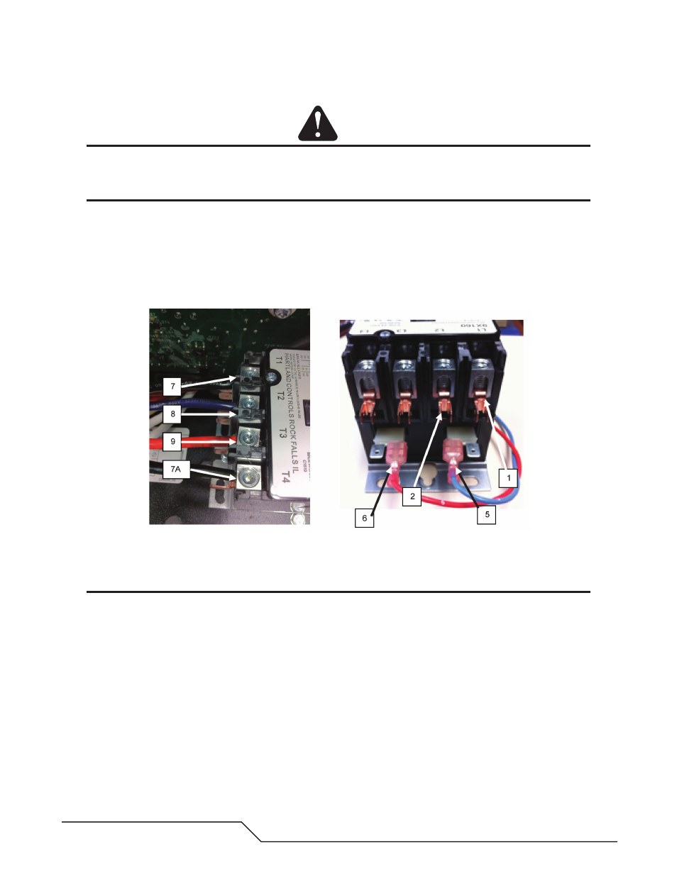
Notations in following illustration designate permanent wire connections to the 9X160 contactor. Addi-
tional connections are noted for single and three phase on the labels internal to the True Series CutMaster
and next to the contactor (if applicable).
7. Reconnect AC power cord as previous. USE T-20 Torx Screwdriver on contactor connection lugs, use needle
nosed pliers on spade connections. CM 12, 20, 25 & 40 UNITS WITH CE FILTERS: Remove wires #5 & #6 from
the contactor and replace with the harness included with the enclosure kit. This will involve clipping wire ties
as in Figure 16. Remove J6 from the Main PCB and replace with the harness connection.
Figure 8: Load Side Connections Figure 9: Line Side Connections
NOTE
An additional #10AWG black wire jumper may be connecting L1 to L4, re-install this, if present and bend
wire to fit the enclosure. See Figure 20.