Removal and replacement, type 1 module, A. disconnect external connections (type 1 module), B. disconnect internal wire harnesses – Tweco 9-9418 User Manual
Page 2
2
Manual 0-4737
Removal and Replacement, Type 1 Module
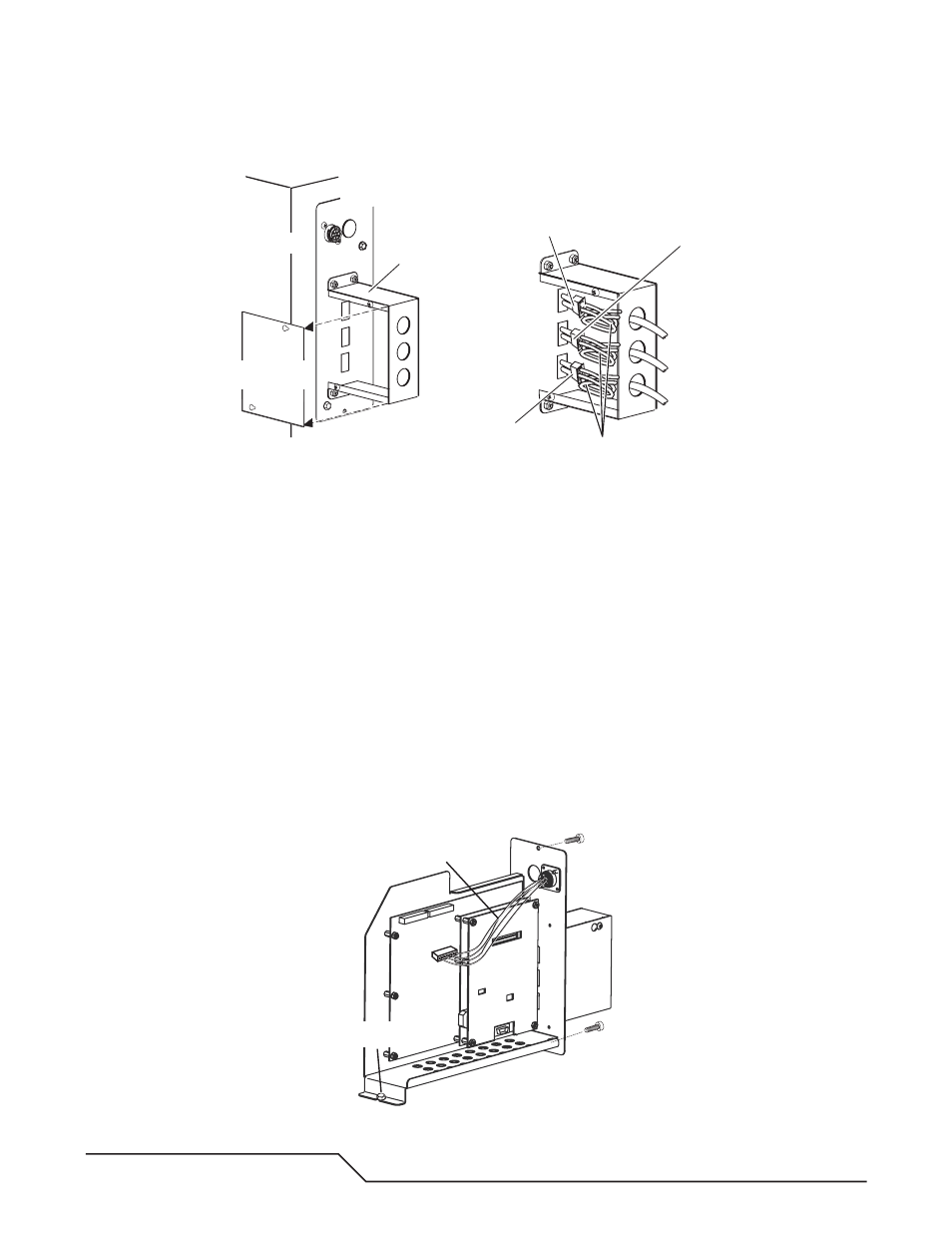
A. Disconnect External Connections (Type 1 Module)
Art # A-06873
Power Supply
Right Side Panel
To Gas Control Module
To Remote HMI
(if installed)
To Slave Power Supply
(if installed)
1
2
Power
Supply
Rear P
anel
Connection Cover
Connection Cover
Side Panel
Cable Loops
1. Remove the side panel from the connection cover.
2. Carefully label and disconnect all external cables connected to the module.
3. Remove and keep the strain relief nut(s) holding the strain relief(s) to the connection cover. Carefully pull the
cable(s) and strain relief(s) out of the connection cover. Leave the strain relief(s) on the cable(s).
B. Disconnect Internal Wire Harnesses
1. A wire harness connects the module rear panel to the larger PC Board in the module. Leave this harness in
place. Carefully label and disconnect all other internal wire harnesses connected to the module. Take care to
label the harnesses connected to terminals J1 and J7 properly to ensure connections to the correct terminals
on the replacement assembly. The harness connectors include latches that must be compressed to release
them from the PC Board receptacles.
2. Loosen, but do not remove, the internal bolt fastening the module to the power supply inner horizontal panel.
3. Remove the hardware holding the module rear panel to the power supply rear panel. Save the hardware for
re-use.
4. Carefully slide the module out of the power supply. Keep the module nearby to serve as a reference for setting
the switches on the replacement module.
Art # A-06874
Internal Bolt
Leave this harness in place