Anti-spatter mist applicator – Tweco QRM-100 User Manual
Page 10
Anti-spAtter mist ApplicAtor
3-6
SM-QRM-100
SECTION 3:
INSTALLATION AND OPERATION
1. Remove the QRM-100 Anti-Spatter Mist Applicator from
the shipping carton.
2. Check to ensure all items shown in Figure 1 are located
and identified. If any of the component parts are missing,
please notify the local Tweco Welding Distributor or
Tweco Products Customer Service Department at
1-800-426-1888.
3. Place the anti-spatter mist applicator as close to the
torch body and cable assembly as possible. This
provides the best control of the amount of anti-spatter
passing through the assembly.
NOTE
the mounting area should allow for integration
to the controlling device and air input supply
lines. these items should be protected by
adequate means if they are subject to welding
spatter or other detrimental surroundings.
4. There are two (2) mounting surfaces provided on the
unit that allows you to choose the best means to work
in your robot cell. Refer to Figure 2 for more complete
detail of the units mounting holes.
Figure 2: Mounting Hole Locations
MOUNTING HOLES
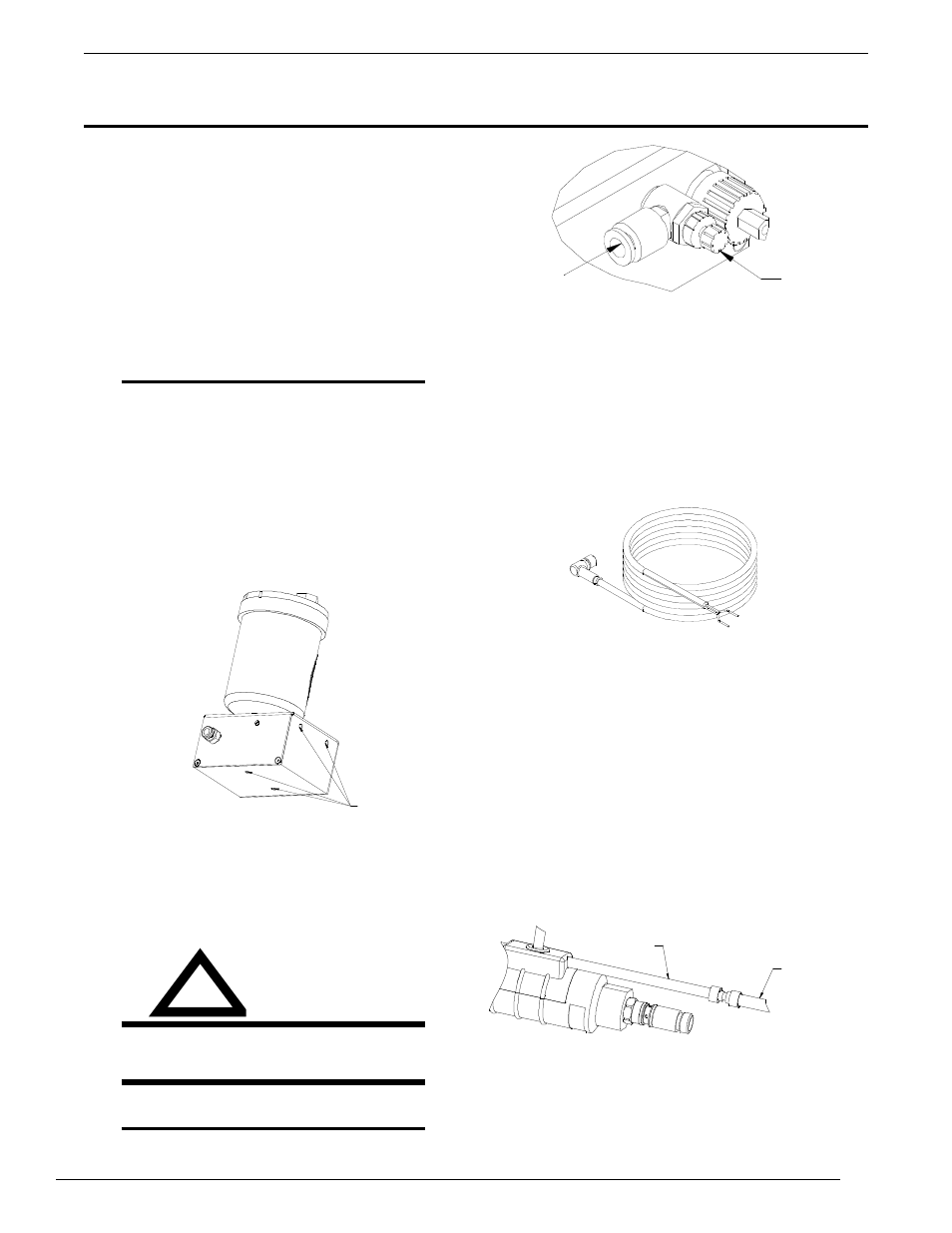
AIR SPEED
CONTROL
INSERT 1/4”
DIAMETER NYLON
TUBE
Figure 3: Compressed Air Connection
9. The unit is supplied with a 10ft. (3m) output hose
assembly. Press the end with the brass connector
into the quick connect fitting on the back of the QRM-
100 Mister. Connect the hose to the purge line of the
robotic torch body and cable assembly by using the
following steps. Refer to Figure 5.
A. Remove the plug from the purge line on the torch
body and cable assembly and slide the steel hose
clamp over the line.
B. Insert the hose splice on the output hose
assembly into the purge line.
C. Secure the hose in place using the steel hose
clamp.
OUTPUT HOSE
ASSEMBLY
FROM MIST
APPLICATIOR
PURGE HOSE FROM
TORCH
Figure 5: Purge Line in Place
7. Connect the control cable to the QRM-100 Mister
assembly.
8. Connect the red/white wire of the control cable to the
positive (+) side of the DC controller. Connect the
green wire to the negative (-) side of the DC controller.
Refer to Figure 4.
Figure 4: Control Cable
inStAllAtion And opeRAtion
5. Secure the mist applicator in place using two
10-24 x 1” long socket head cap screws.
6. Use a 1/4” nylon tube for the compresed air line to
the unit, connect the airline to the fitting, and secure.
Refer to Figure 3.
WARNING
neveR uSe oxygen With the QRM-100 Anti-
SpAtteR MiSt ApplicAtoR.
NOTE
the air line should be connected to an air
regulator capable of delivering 80 to120 psi.
!
!