Conductor tube alignment fixture – Tweco QCT-1 User Manual
Page 12
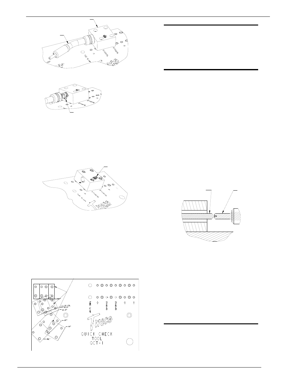
CONDUCTOR TUBE ALIGNMENT FIXTURE
3-8
QCT-1
inSTAllATion And opeRATion
REAR ALIGNMENT
BLOCK ASSEMBLY
CONDUCTOR TUBE
ASSEMBLY
STAINLESS STEEL PINS
Figure 10: Conductor Tube/rear Alignment Block
Assembly
9. Insert the factory supplied 5/32” allen wrench into the
conductor tube locking screw on the rear alignment
block assembly. Rotate the screw clockwise until the
conductor tube is held in place. Refer to Figure 11.
CONDUCTOR TUBE
LOCKING SCREW
Figure 11: Conductor Tube Locking Screw on Rear
Alignment Block Assembly
10. Remove the two 5/16”-18 socket head cap screws
from the front alignment block assembly.
11. Locate the assembly according to the conductor tube
assembly degree of bend. (eg., if the conductor tube
bend equals 22.5°, set the front alignment assembly in
the 22.5° location on the fixture). Refer to Figure 12.
ALIGNMENT
LOCATIONS
Figure 12: Outline of Front Alignment Block Locations
NOTE
The front alignment block can be positioned
in the following positions on the alignment
fixture:
180° - 18° - 22.5° - 22.5°l - 45° - 45°l
- 60°
NOTE
There are two bullet nose dowel pins pressed
into position on the under side of the front
alignment block assembly. The dowel pins
must be aligned with the drill bushings that
are in the fixture plate.
12. Secure the front alignment block into position with the
5/16”-18 socket head cap screws removed in Step 10.
13. While holding the alignment sleeve assembly on the
front alignment block, slide the alignment sleeve pin
forward until it contacts the brass alignment pin on the
conductor tube.
14. Verify that the machined point on the alignment sleeve
pin is centered to the small hole in the brass alignment
pin. If the alignment sleeve pin is centered properly, the
alignment sleeve will slide over the brass alignment pin.
This indicates that no adjustments would be required on
the conductor tube assembly. Refer to Figure 13.
Figure 13: Alignment Sleeve Pin and Brass Alignment Pin
BRASS
ALIGNMENT
PIN
ALIGNMENT
SLEEVE PIN
15. Remove the front alignment block assembly from the
fixture plate by removing the two 5/16”-18 socket
head cap screws.
16. Remove the conductor tube assembly from the rear
alignment block assembly by rotating the conductor
tube locking screw counterclockwise.
17. Remove the nozzle spacer and the brass alignment pin
from the conductor tube assembly and replace these
items with the standard diffuser, tip, and nozzle.
NOTE
on the QTRW series conductor tube assemblies,
be sure the insulator ring is in place between
the conductor tube and diffuser.
18. The conductor tube assembly is now ready to be put
into operation.