Conductor tube alignment fixture – Tweco QCT-1 User Manual
Page 10
CONDUCTOR TUBE ALIGNMENT FIXTURE
3-6
QCT-1
SECTION 3:
INSTALLATION AND OPERATION
1. Remove the QCT-1 alignment fixture from the
wooden shipping crate. Check to ensure all items
shown in Figure 1 are located and identified. If any of
the component parts are missing, please notify the
local Tweco Welding Distributor or Tweco Products
Customer Service Department at 1-800-426-1888.
2. Mount the alignment fixture to a solid worktable within
close proximity of the robot cell. The fixture base has
two 1/2” (12,70mm) holes, counter bored to accept
a 1/2” socket head cap screws (not supplied). Refer
to Figure 2.
MOUNTING
HOLES FOR 1/2”
SOCKET HEAD
CAP SCREW
Figure 2: Fixture Mounting
The rear alignment block assembly is positioned
and set in the “STANDARD” location on the fixture.
This location will allow any of the standard QTR and
QTRW series conductor tubes to be adjusted without
relocating the rear alignment block assembly. Refer
to Figure 3.
REAR ALIGNMENT BLOCK
ASSEMBLY
MARKED “STANDARD”
FOR POSITIONING
Figure 3: Rear Alignment Block Assembly in Standard
Position
NOTE
if the conductor tube assembly is not a
“STAndARd”, relocate the rear alignment
block assembly by following the steps listed
below.
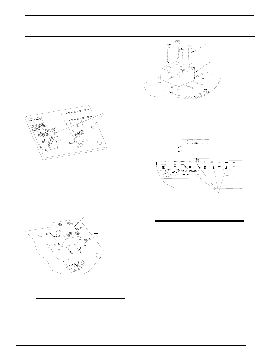
A. Remove the four 5/16”-18 socket head cap screws
on the alignment block assembly. Refer to Figure 4.
5/16-18” MOUNTING
SCREWS
REAR ALIGNMENT
BLOCK ASSEMBLY
Figure 4: Rear Alignment Block Assembly and Mounting
Screws
B. The fixture plate allows the rear alignment block
assembly to be moved in 1.525” (38,74mm)
increments. Refer to Figure 5.
BUSHINGS
Figure 5: Bushing Location for Rear Alignment Lock
Assembly
NOTE
There are two bullet nose dowel pins pressed
into position on the under side of the rear
alignment block assembly. The dowel pins
must be aligned with the drill bushings that
are in the fixture plate.
C. Position the rear alignment block assembly to
meet your specific requirements.
D. Re-insert and tighten the 5/16”-18 socket
head cap screws into the rear alignment block
assembly.
3. Remove the gas nozzle, diffuser and contact tip from
the conductor tube assembly.
4. Select the correct alignment pin for the specific
conductor tube assembly being adjusted. Thread and
wrench tighten this alignment pin on the conductor
tube assembly. Refer to Figure 6 and Table 1.
inSTAllATion And opeRATion