Conductor tube alignment fixture – Tweco QCT-1 User Manual
Page 11
CONDUCTOR TUBE ALIGNMENT FIXTURE
3-7
QCT-1
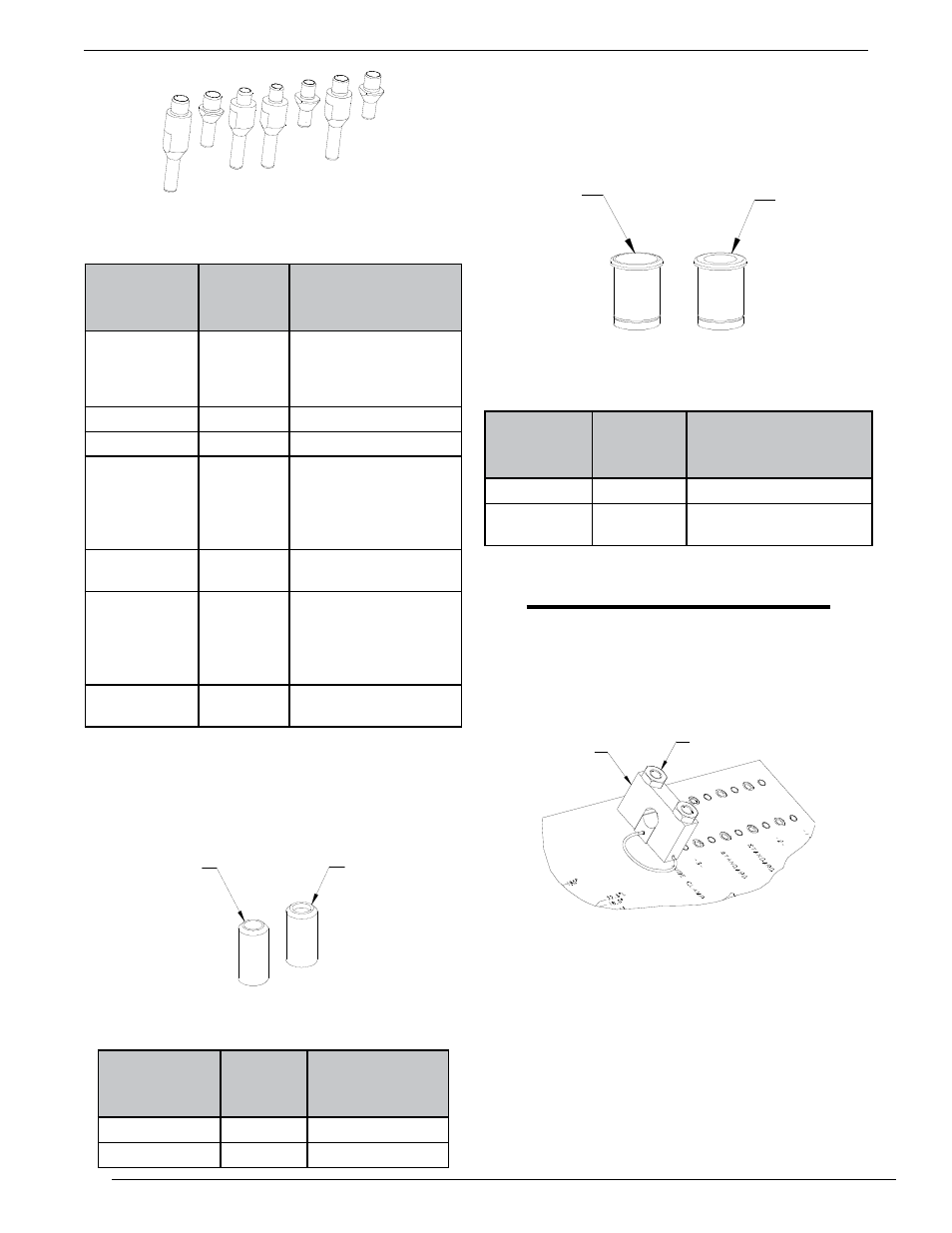
Figure 6: Alignment Pins
inSTAllATion And opeRATion
Alignment Pin
Part No.
Alignment
Pin Stock
No.
Conductor Tube
Assembly
QCT-QTR
3500-1363 QTR66-18, QTR66-
180, QTR66-180L,
QTR66-22, QTR66-22L,
QTR66-45L, QTR66-60
QCT-QTRL
3500-1364 QTR66-45
QCT-QTRW63 3500-1365 QTRW63 Series (All)
QCT-QTRW64 3500-1366 QTRW64-18, QTRW64-
180, QTR64-180-L,
QTRW64-22, QTRW64-
22L, QTRW64-45L,
QTRW64-60
QCT-
QTRW64L
3500-1367 QTRW64-45
QCT-QTRW66 3500-1368 QTRW66-18, QTRW66-
180, QTRW66-180L,
QTRW66-22, QTRW66-
22L, QTRW66-45L,
QTRW66-60
QCT-
QTRW66L
3500-1369 QTRW66-45
5. Select the correct nozzle spacer for the specific
conductor tube assembly being adjusted. Refer to
Figure 7 and Table 2.
Nozzle Spacer
Part No.
Nozzle
Spacer
Stock No.
Conductor Tube
Assembly
QCT-24
3500-1360 QTRW64 Series
QCT-26
3500-1361 QTRW66 Series
QCT-24-A
1.000” O.D.
25.4MM
QCT-26-A
1.063” O.D.
27MM
Figure 7: Nozzle Spacers
Table 2: Nozzle Spacer/Conductor Tube Assembly
Table 1: Alignment Pin/Conductor Tube Assembly
6. Select the correct head spacer for the nozzle spacer
and conductor tube assembly being adjusted. The head
spacer will need to be inserted into the adjustment bar
assembly. Secure the head spacer with the set screw
on the adjustment assembly. Refer to Figure 8 and
Table 3.
QCT-8S-1A
1.020” I.D.
25,91MM
QTC-8S-2A
.790” I.D.
20,07MM
Figure 8: Head Spacer
Head Spacer
Part No.
Head
Spacer
Stock No.
Conductor Tube
Assembly
QCT-8S-1
3500-1355 QTRW64
QCT-8S-2
3500-1356 QTR66 AND QTRW63
Series
Table 3: Head Spacer/conductor Tube Assembly
NOTE
no head spacer is required for QTRW66 Series
conductor tube assembly.
7. Remove the two 1/2” hex nuts from the block clamp
assembly. Refer to Figure 9.
CLAMP BLOCK
HEX NUTS
Figure 9: Tube Clamp in Position With 1/2” Hex Nuts
8. Remove the block clamp assembly and insert the
conductor tube assembly into the rear alignment
block assembly. The two stainless steel locating pins
protruding from the rear alignment block will align
the conductor tube on the alignment fixture. Refer to
Figure 10.