18 setup for manual arc (mmaw) welding, Transtig 170ti – Tweco 170Ti Transtig User Manual
Page 36
TRANSTIG 170Ti
INSTALLATION, OPERATION AND SETUP
3-18
Manual 0-5279
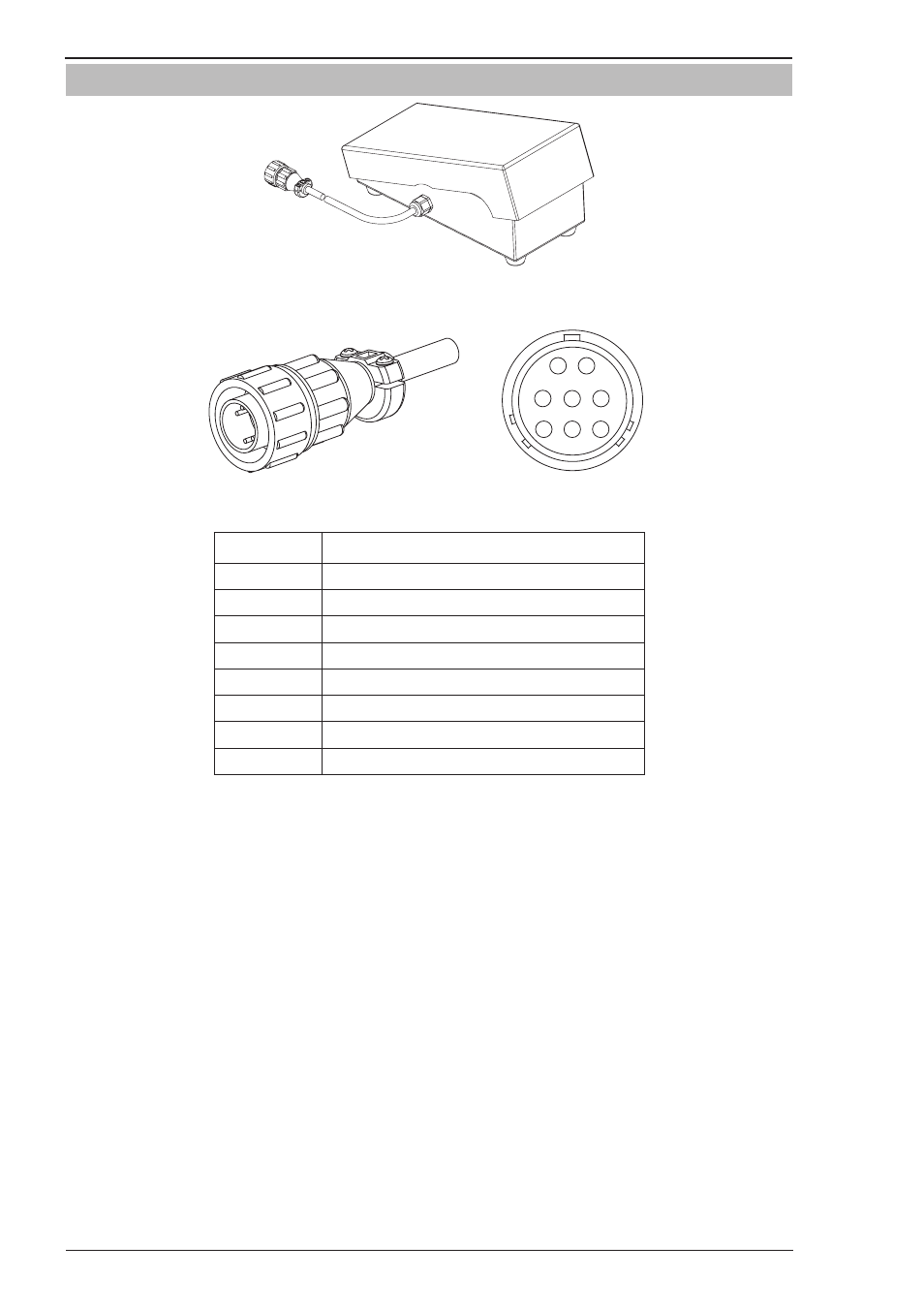
3.09 Foot Control Part No. W4015800 (Optional Accessory)
Art # A-11338
Figure 3-8: Foot Control
Art # A-11339
1
2
3
4
5
6
7
8
Art # A-11340
Figure 3-9: 8 Pin Control Plug
Pin
Description
1
Not Used
2
Trigger Switch
3
Trigger Switch
4
Not Used
5
Potentiometer Maximum
6
Potentiometer Minimum
7
Potentiometer Wiper
8
Not Used
Table 3-2
Description
The CIGWELD Foot Control is a foot operated switch and potentiometer which starts and stops the welding
process and controls welding current through operation of the foot pedal. Refer to list below for compatible
Cigweld power sources.
Installation
Attach the 8-pin connector on the end of the cable to the 8-pin receptacle on the front of the welding machine.
To complete the connection, align the keyway, insert the plug, and rotate the threaded collar fully clockwise.
Foot Control Operation
Press the foot pedal to start the machine output functions. The foot control potentiometer controls the welding
current up to the level set on the welding power source. Note that the maximum current must be set on the
power source by the operator prior to the foot control being connected, although this can be adjusted while
you are welding.
With the foot control connected, the power source will only display minimum preview Amps until the foot
control is depressed then it displays actual welding current when welding. Pressing the pedal to increases
the welding current; letting up on the pedal decreases the welding current. Releasing the pedal completely
extinguishes the arc and initiates the post-flow shielding gas timer (where fitted).