09 feed monitor operating procedure, 10 system dip switches, Ultrafeed va 2000 – Tweco VA 2000 Ultra-Feed User Manual
Page 36
ULTRAFEED VA 2000
4-10
February 27, 2006
4.09 Feed Monitor Operating Procedure:
GENERAL DESCRIPTION:
The feed monitor display is a visual tool that can be used to
check the feeding characteristics of the feed system. The
display is a LED bar graph with ten individual segments.
The first three segments are green; the next four segments
are yellow, and the last three segments are red. The display
can be activated by depressing the gun switch trigger or the
inch switch.
The feed monitor display is a feature to aid the operator in
determining when it is time to replace tips, liners, wire guides,
or feed rolls. As the contact tip, liner, wire guides, or feed
rolls become dirty or worn due to normal operating
conditions, the user will see an increase in the number of
lighted LED’s on the feed monitor display.
If any of the red segments on the bar graph were to light for
a period of time, the system has entered an overload
condition and should be shutdown until the problem is
diagnosed and corrected.
NOTE
When the gun switch or inch switch is first
depressed, the red segments may come on for
a very short period of time until the preset wire
feed speed has been reached. This condition is
caused by the acceleration of the motor and is
normal; the system is not in an overload
condition. Only when the red segments remain
on after the wire feeder has reached preset wire
feed speed is the condition considered to be an
overload condition.
OPERATING PROCEDURE:
To use the feed monitor display, follow the steps listed below.
1. Check initial condition of the contact tip, liner, wire guides,
and feed rolls to insure they are all in good working
condition.
2. Set the desired wire feed speed.
3. Pull the gun switch trigger or depress the inch switch
NOTE
Welding wire is electrically “hot” if the gun switch
is pulled). The monitor should illuminate a
consistent number of LED bars. Fluctuations of
more than two bars could indicate a feeding
problem.
4. Note any increase in the number of bars illuminated.
This could be an indication that a change in the tip, liner,
wire guides, or feed rolls may be necessary.
4.10 System DIP Switches
The Motor Control PC Board contains a 5 position DIP
switch that allows the user to (1) optimize the run-in time
setting of the system for a particular application and (2)
set the wire feed speed meter to display in inches per
minute (IPM) or meters per minute MPM).
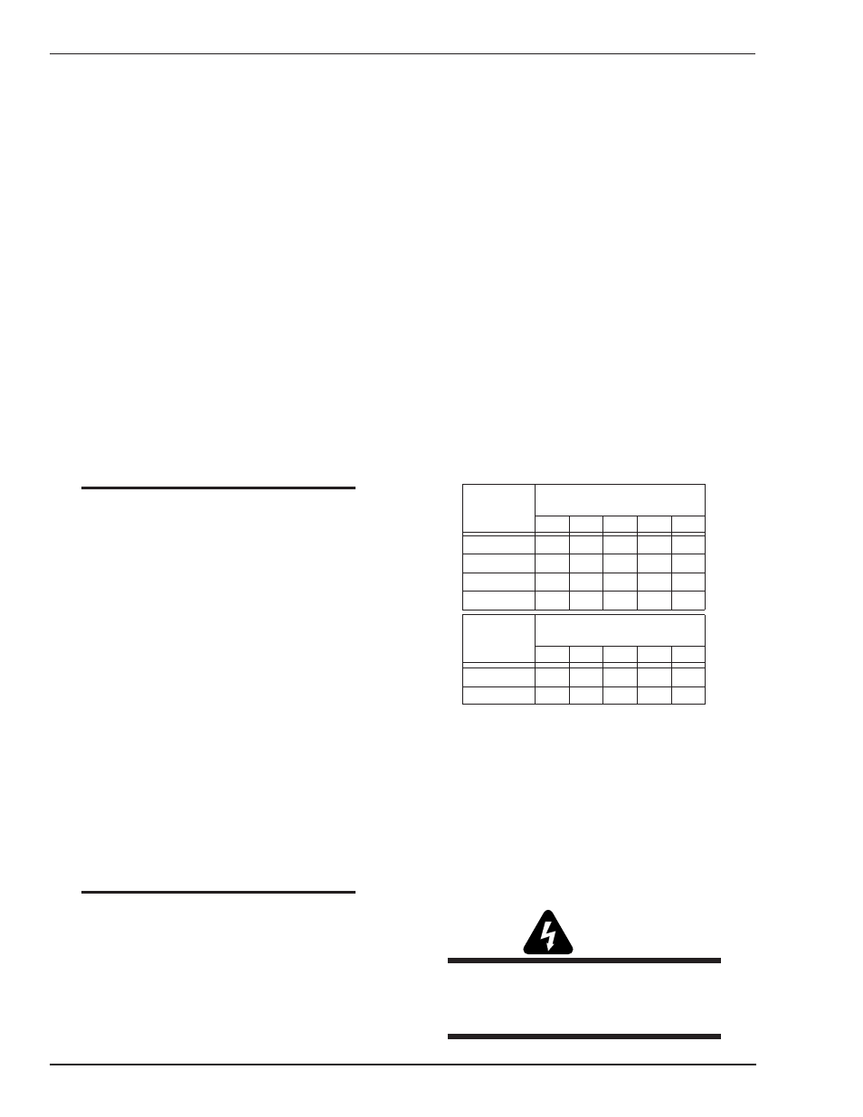
RUN-IN TIME ADJUSTMENT:
The run-in time is defined as the time required for the
wire to reach preset wire feed speed from a stationary
condition. The VA 2000 has been shipped from the factory
in a 0.2 second run-in time configuration (DIP switch 2
closed; DIP switches 1, 3 open). However, the run-in time
setting can be increased or decreased accordingly with
the Figure 4-6 adjustments.
ENGLISH/METRIC SELECT:
The meter may display wire feed speed in IPM by selecting
DIP Switch Position 5 to be closed. It will display in MPM
by selecting DIP Switch Position 5 to be open.
RUN IN
RUN IN
TIME
TIME
0.1 SEC
0.1 SEC
POSITION
POSITION
DIP SWITCH
DIP SWITCH
1
2
3
4
5
0.2 SEC
0.2 SEC
0.3 SEC
0.3 SEC
0.4 SEC
0.4 SEC
X
O
O
O
O
X
O
X
O
O
O
O
METER
METER
WFS
WFS
DIP SWITCH
DIP SWITCH
POSITION
POSITION
3
1
2
5
4
MPM
MPM
IPM
IPM
X
O
DISPLAY
DISPLAY
X=CLOSED
X=CLOSED
O=OPEN
O=OPEN
- =NOT USED HERE
- =NOT USED HERE
-
-
-
-
-
-
-
-
-
-
-
-
-
-
-
-
Art # A-07387
Figure 4-6: System DIP Switch
To make an adjustment to the system DIP switches, the
control box sheet metal cover and door will have to be
removed to expose the motor control PC board.
PROCEDURE:
WARNING:
ELECTRIC SHOCK CAN KILL. Remove input
power from the wire feeder before making an
adjustment to the system DIP switches.