Fabricator 252i installation/setup – Tweco 252i Fabricator User Manual
Page 56
FABRICATOR 252i
INSTALLATION/SETUP
INSTALLATION/SETUP 3-26
Manual 0-5155
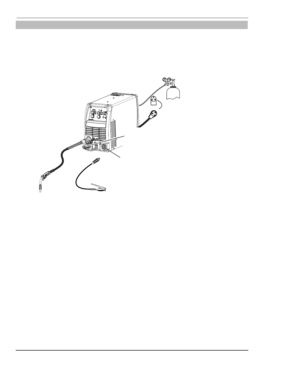
3.18 Set-up MIG (GMAW) Welding with Gas Shielded MIG Wire
The Fabricator 252i is supplied with a Tweco Fusion 250 AMP air-cooled MIG Gun. The Tweco Fusion 250A MIG Gun
is designed with an ergonomic handle and fewer parts to cause performance problems. The Fusion MIG Gun uses
standard readily available Tweco Velocity consumable parts.
When using a non shielded wire, you need to have an external gas source attached to the unit.
For most Non Shielded Wire, connect the Work Lead to the negative - terminal and connect the MIG Gun polarity lead
to the positive + terminal. If in doubt, consult the MIG electrode wire manufacturer.
+
-
Art # A-10550
Connect MIG Gun Polarity
Terminal to +/Positive
(Dinse® type 50)
Negative Output
Terminal
(Dinse® type 50)
Ensure that the gas
cylinder is secured to
a building pillar, wall
bracket or otherwise
securely fixed in an
upright position.
Figure 3-20: MIG Gun Polarity Positive
1. Turn the Main ON/OFF switch OFF (located on the rear panel).
2. Check that the MIG wire size, contact tip, MIG Gun liner and drive roll groove are all the same size before fitting
the MIG wire into the Power Source.
3. Connect the MIG Gun Polarity Lead to the positive welding terminal (+). If in doubt, consult the MIG electrode
wire manufacturer. Welding current flows from the Power Source via heavy duty bayonet type terminals. It is
essential, however, that the male plug is inserted and turned securely to achieve a sound electrical connection.
4. Fit the MIG wire spool and Fusion MIG Gun to the Power Source. (Refer to section 3.08 to 3.12 ).
5. Connect the work lead to the negative welding terminal (-). If in doubt, consult the MIG electrode wire manu-
facturer. Welding current flows from the Power Source via heavy duty bayonet type terminals. It is essential,
however, that the male plug is inserted and turned securely to achieve a sound electrical connection.
6. Fit the welding grade shielding gas regulator/flow gauge to the shielding gas cylinder (refer to Section 3.17)
then connect the shielding gas hose from the rear of the power source to the regulator/flow gauge outlet.
7. Turn the Main ON/OFF switch ON (located on the rear panel).
8. Select MIG mode with the process selection control. (Refer to Section 3.06.3 for further information)
9. Remove the Fusion MIG Gun nozzle and contact tip.
10. Depress MIG Gun trigger to feed the MIG wire out. Then fit the contact tip on the MIG wire and hand tighten
the nozzle in place.
11. Refer to the Weld Guide located on the inside of the wire feed compartment door for further information on
Voltage/Wirespeed settings.