Ultra-cut 300 – Tweco 300 Ultra-Cut(March 2013) User Manual
Page 66
INSTALLATION
3-42
Manual No. 0-5134
ULTRA-CUT 300
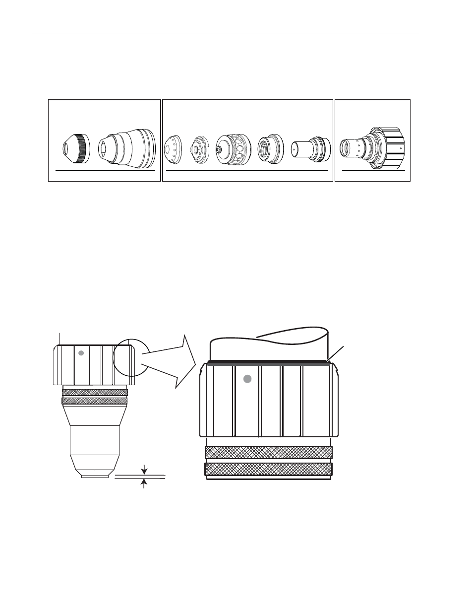
1. Check the appropriate cut chart for the right combination of parts for the cutting application.
2. For 200 Amp parts only, thread the Shield Retainer onto the Shield Cup.
3. Stack the consumable parts together.
Shield
Retainer
Shield Cup
Shield Cap S
hield Ga
s
Di
str
ibu
to
r
Tip
Pla
sma Ga
s
Di
str
ibu
to
r
Elect
rode
Ca
rtr
idge
Art # A-08303
A
B
C
1 - Assemble “A” 200 A only.
2 - Assemble “B”.
3 - Assemble “B” to “C”.
4 - Assemble “A” to “B-C” assembly.
4. Insert the stack of consumable parts into the cartridge. Ensure that the large O-ring on the torch tip fits
completely into the cartridge. If any part of the O-ring protrudes from the cartridge, the parts are not
seated properly.
5. Use the cartridge tool to hold the cartridge assembly, while turning the shield cup (and shield retainer
for 200 Amp parts) onto the cartridge assembly. For 300 Amp parts turn the shield retainer onto the
shield cup now. When this group is fully assembled, the shield should protrude from the front of the
shield cup or shield retainer. Without this protrusion the shield cup is not properly tightened onto the
cartridge assembly.
6. Take the cartridge tool off the cartridge. Fit the cartridge assembly onto the torch head. The Speed Lok
ring should clidk into place and the cartridge assembly should touch the large O-ring on the torch body.
Torch Head O-Ring
Torch Head
Art # A-08300_AB
0.063 - 0.083"
(1.6 - 2.1 mm)
Protrusion
Installing Assembled Cartridge Onto Torch Head
6. Slide the ohmic clip over the shield cup if using ohmic torch height sensing.