Tweco SC-6 Standoff Control User Manual
Tweco Equipment
1
SC-6 STANDOFF CONTROL INSTALLATION 0-2454
WARNING
Disconnect primary power at the source before assembling or disassembling
stacked modules, individual modules, torch parts, or torch and leads assemblies.
Introduction
Parts of the SC-6 Standoff Control must be installed inside the STAK PAK
®
Control Module Assembly. The
instructions in this Appendix covers only the installation of those parts.
WARNING
These instructions are for STAK PAK
®
Control Modules with serial number
M40621A185010A and later only.
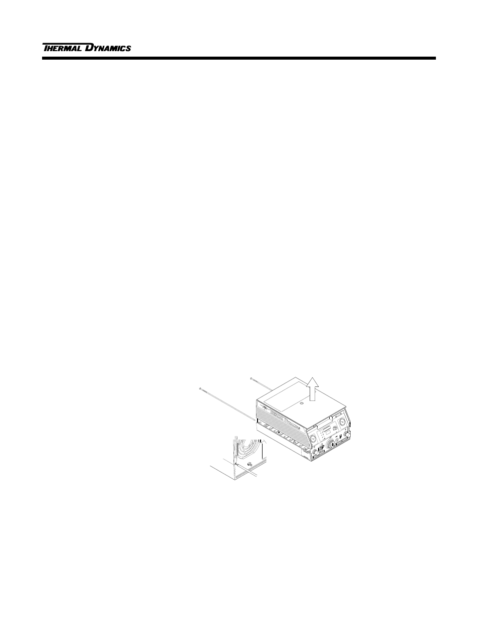
Opening the Enclosure
The upper half of the control module enclosure must be removed to install the wire harness and SC-6 Voltage
Divider PC Board (Refer to Figure 1):
1. Unscrew and remove the two module assembly pins which secure the upper control module enclosure to
the lower.
2. Lift the upper enclosure from the control module.
CONTROL
MODULE
CM 6030
RUN
PURGE
SET
ON
WORK
STANDARD
TORCH
LATCH
A
CURRENT
TEMP
AC
GAS
DC
PILOT
CSD
AMPS
PLASMA
GAS
SECONDARY/
SINGLE GAS
STAK PAK
Remove the two module
assembly pins from rear panel
(see pin removal detail below).
Lift the upper
enclosure from
the control module.
Use a flat blade screwdriver
to pry the pin outward from
the top until threads engage,
then use a phillips head
screwdriver to fully
remove the pin
Pin Removal Detail (Reverse View)
Figure 1 - Opening the Control Module Enclosure
Installing SC-6 Voltage Divider PCB Assembly
Refer to Figure 2 and install the SC-6 Voltage Divider PCB Assembly as follows:
10/14/94