07 optional power supply settings, 07 optional power supply settings -7 – Tweco CE PAK Master 150XL With Latch Circuit User Manual
Page 33
Manual 0-2865
4-7
OPERATION
WARNINGS
Disconnect primary power at the source before as-
sembling or disassembling power supply, torch
parts, or torch and leads assemblies, or adding cool-
ant.
It is not enough to simply move the ON/OFF
switch on the unit to OFF position when cutting
operations have been completed. Always open the
power supply disconnect switch five minutes after
the last cut is made.
A. Operational Suggestions
The suggestions below should be followed in all cutting
and gouging operations:
1. Wait five minutes before setting the ON/OFF switch
to OFF after operation. This allows the cooling fan to
run to dissipate operating heat from the power sup-
ply.
2. For maximum parts life, do not operate the pilot arc
any longer than necessary.
3. Use care in handling torch leads and protect them from
damage.
4. In continuous cutting applications using CO2, it is of-
ten necessary to manifold four to six cylinders together
to maintain adequate flow at operating pressures.
B. Fold Back Feature
Should the torch tip contact the workpiece or molten
slag, the output current will immediately drop to 35
amps to minimize potential tip damage.
4.07 Optional Power Supply
Settings
The following functions can be used to tailor a system for
special application requirements or unique user prefer-
ences. These functions are controlled by DIP switches
located on the Logic Control PC board in the power sup-
ply.
Remove the left side panel and locate the Logic Control
PC Board near to top center of the unit. Set the function
as required.
A. High/Low Speed Auto-Restart Function
(SW5)
The Plasma Power Supply is always in the Auto-Restart
mode. This means that at the end of the cut, if the START
signal is still on, the pilot will restart automatically.
An immediate pilot restart, when cutting over holes or
expanded metal at relatively slow speeds, may cause the
arc to transfer back to the piece just cut. This happens
because the torch has not had time to be moved away
from the cut piece and results in extra starts and unnec-
essary parts wear.
The High/Low Speed Auto-Restart switch, SW5, has two
settings as follows:
• Low Speed - adds a one-tenth second delay to
the pilot restart to prevent arc back conditions.
• High Speed - no delay required as it may delay
starting on the next edge.
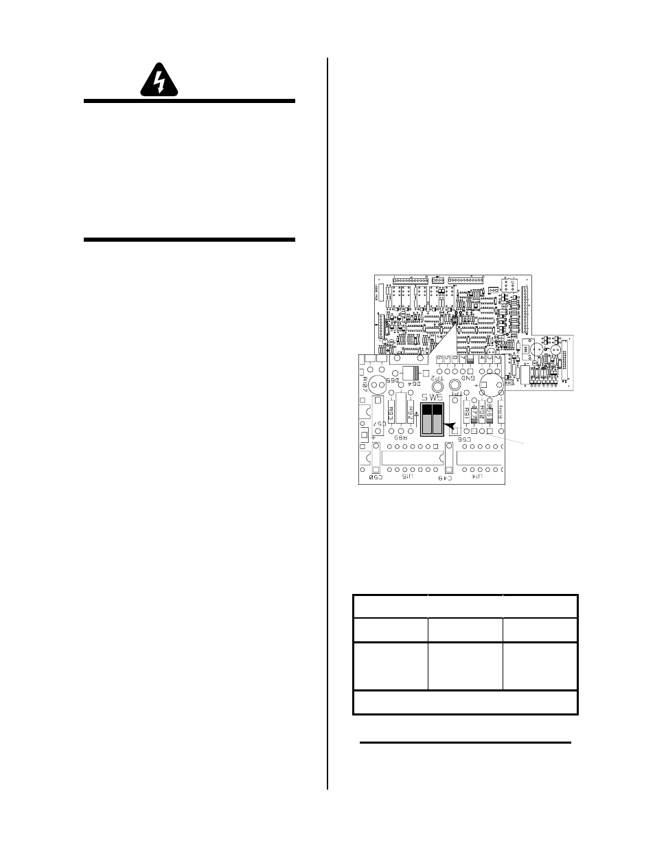
A-02258
Logic PC Board
SW5
1 2
Figure 4-7 High/Low Speed Auto-Restart Switch
SW5 Location
Select the desired function as shown in the following
chart:
High/Low Speed Auto-Restart Function
Speed
SW5-1
SW5-2
High
0 (OFF)
0 (OFF)
Low *
1 (ON)
1 (ON)
* = Factory Setting
NOTE
The ON position is in the direction of the arrow on
the PC Board next to the switch.