05 connecting torch, 06 gas selection, 05 connecting torch -2 3.06 gas selection -2 – Tweco 300 Maximizer User Manual
Page 20
INSTALLATION
3-2
Manual 0-2554
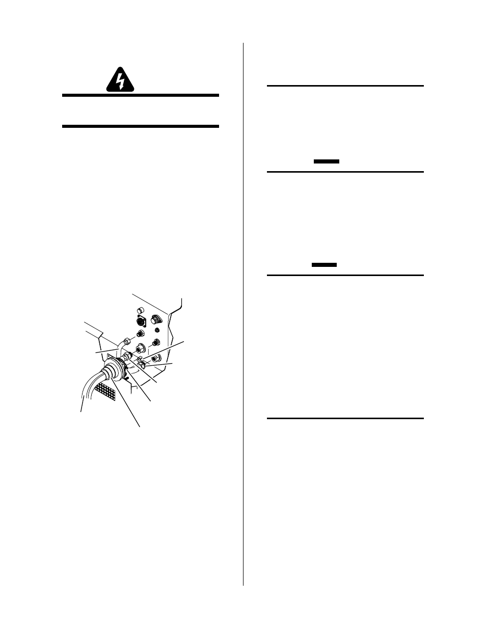
3.05 Connecting Torch
WARNING
Disconnect primary power at the source before dis-
assembling the torch or torch leads.
The Torch Leads connect directly to a bulkhead inside
the Power Supply. Connect the Torch Leads per the fol-
lowing procedure:
1. Remove the tape securing the shield of the torch leads
to the leads.
2. Unfold the shield towards the end of the leads.
3. Feed the torch leads through the boot on the front
panel of the Power Supply.
4. Feed the torch leads through the supplied Hose
Clamp.
5. Connect the torch leads connectors to the bulkhead
connections.
Secondary
Gas Lead
Torch Leads
Extension
Assembly
Hose Clamp
Torch Leads
Extension Boot
Coolant Return
Lead
Coolant Supply
Lead
Plasma
Gas Lead
A-01008
Figure 3-2 Torch Leads Connection to Power
Supply
6. Pull the shielding braid towards the front panel as far
as it will go up and over the brass hub. The hub is
part of the Boot Assembly and provides the ground-
ing point for the shielding in the torch leads.
7. Place the hose clamp over the shield and hub. Tighten
the hose clamp to secure the shielding braid to the
hub.
NOTE
Make sure that the shielding braid is pulled back
as far as possible from the bulkhead connections.
Leave any extra shielding braid between the hose
clamp and the front panel area.
8. Check the torch for proper parts assembly.
CAUTION
The torch parts (gas distributor, electrode, tip, and
shield cup) must correspond with plasma and sec-
ondary selection, output current level, and type of
operation (cutting or gouging). Refer to Section
4.04, Torch Parts Selection.
3.06 Gas Selection
CAUTIONS
Maximum input gas pressure must not exceed 125
psi (8.6 bar)
Air supply must be free of oil, moisture, and other
contaminants. Excessive oil and moisture may
cause double-arcing, rapid tip wear, or even com-
plete torch failure. Contaminants may cause poor
cutting performance and rapid electrode wear.
The type of operation will determine the best gases to be
used. Refer to the following and select the plasma and
secondary gases that best fit the operation(s):
A. Plasma Gases
NOTE
Refer to Appendix 2, Cutting Speed Charts, for
proper gas pressure and flow rates.
1. Air Plasma
• Most often used on ferrous or carbon base materi-
als to obtain good quality at faster cutting speeds.
• Air plasma is normally used with air secondary.
• Only clean, dry air is recommended for use as
plasma gas. Any oil or moisture in the air supply
will substantially reduce torch parts life.
• Provides satisfactory results on nonferrous materi-
als.