Cdv series direct vent gas fireplace, Vertical through-the-roof installation – Vermont Casting 36CDVRRN User Manual
Page 25
25
CDV Series Direct Vent Gas Fireplace
20010175
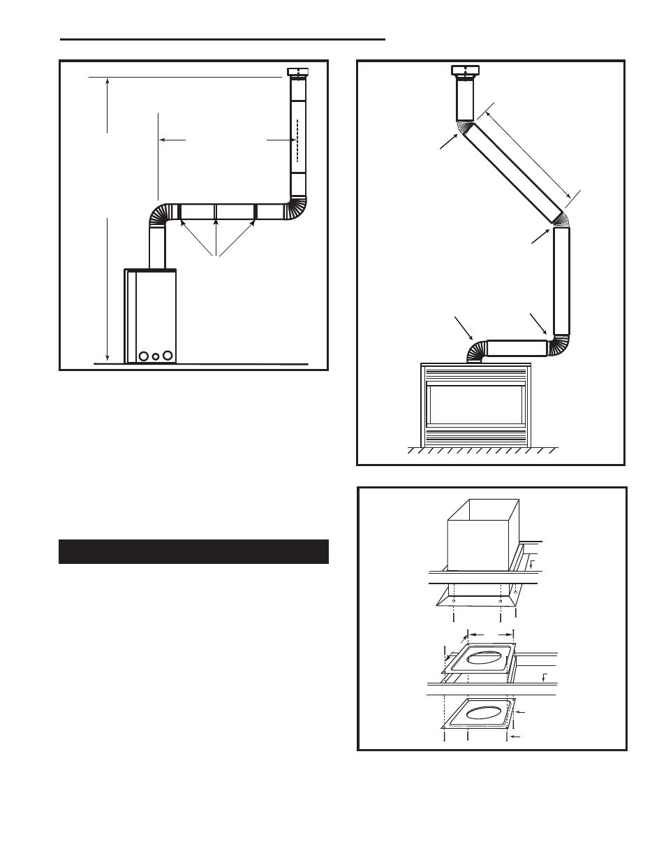
Max. 10' (3m)
Max. Height
40' (12m)
Min. Height
7���' (2.3m)
FP1244
through the roof
max/min dims
12/02
Pipe Straps Every
3’ (914mm)
FP1244
Fig. 51 Support straps for horizontal runs.
•
Two sets of 45° elbows offsets within these vertical
installations. From 0 to a maximum of 8’ (2.m) of
vent pipe can be used between elbows. (Fig. 52)
•
7DVCS must be used to support offsets. (Fig. 54)
This application will require that you first determine
the roof pitch and use the appropriate starter kit.
(Refer to Venting Components List)
•
The minimum height of the vent above the highest
point of penetration through the roof is 2’ (610 mm).
(Fig. 56)
1
2
3
4
Max. 8' (2.4m)
FP1245
through the roof
90 & 45 degree
12/02
1 + 2 + 3 + 4 = 270°
FP1245
Fig. 52 Typical offset application.
Vertical Through-the-Roof Installation
1. Locate your fireplace.
2. Plumb to center of the (4” (102 mm) flue collar from
ceiling above and mark position.
3. Cut opening equal to 9³⁄₈” x 9³⁄₈” (240 x 240 mm).
4. Proceed to plumb for additional openings through the
roof. In all cases, the opening must provide a minimum
of 1” (25 mm) clearance to the vent pipe, i.e., the hole
must be at least 9³⁄₈” x 9³⁄₈” (240 x 240 mm).
5. Place fireplace into position.
6. Place firestop(s) #7DVFS or Attic Insulation Shield
#7DVAIS into position and secure. (Fig. 53)
7. Install roof support (Fig. 54) and roof flashing making
sure upper flange of flashing is below the shingles.
(Fig. 54)
8. Install appropriate pipe sections until the venting is
above the flashing. (Fig. 54)
CFM100
Firestop-Vertical
09/20/00
11"
11"
Attic Insulation
Shield
Joist
Ceiling In-
stallation
Joist
Upper Floor
Firestop Spacer
Nails (4)
CFM100a
Fig. 53 Place firestop spacer(s) and secure.