Cdv series direct vent gas fireplace, Vertical sidewall installation – Vermont Casting 36CDVRRN User Manual
Page 17
17
CDV Series Direct Vent Gas Fireplace
20010175
Vertical Sidewall Installation
STEP 1
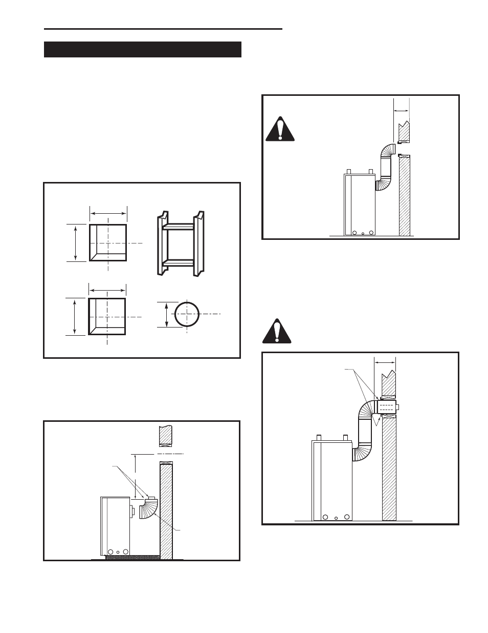
Locate vent opening on the wall. It may be necessary
to first position the fireplace and measure to obtain hole
location. Depending on whether the wall is combustible
or noncombustible, cut opening to size. (Fig. 26)
For combustible walls first frame in opening.
Combustible Walls (Fig. 26): Cut a 9³⁄₈”H x 9³⁄₈” W
(240 x 240 mm) hole through the exterior wall and
frame.
Noncombustible Walls (Fig. 26): Hole opening must
be 7.5” (190 mm) in diameter.
VO584-100
Vent Opening
2/99 djt
Vent Opening for Combustible Wall
9³⁄₈”
(240mm)
9³⁄₈”
(240mm)
Fireplace Hearth
Framing Detail
Opening for Noncombustible Wall
7¹⁄₂”
(190mm)
VO584-100
Fig. 26 Locate vent opening on wall.
STEP 2
Slide venting component on collar of fireplace. Secure
component to fireplace by running a screw (self-tap-
ping) through tab & into outer casing. (Fig. 27)
CFM136
Rear Vent horizontal length
2/26/01 sta
X
Always install hori-
zontal venting on a
level plane.
CFM136
Fig. 28 Measure horizontal length including 2” overlap.
�
CFM143
2/2/01 sta
Ensure Pipes are
Concentric
CFM143a
Fig. 27 Always start vertical run with 7TCDV90 on 36CDVR
unts.
7TCDV90
STEP 3
Measure the horizontal length requirement including a
2” (51 mm) overlap, i.e. from the elbow to the outside
wall finish plus 2”, or the distance required if installing a
second 90° elbow. (Fig. 28)
STEP 4
Use appropriate length of pipe section - telescopic or
fixed - and install the horizontal vent sections. A starter
section of pipe which goes through the wall is packaged
with the 7TCRVT kit, and can be cut to suit if necessary.
(Fig. 29)
Sealing between the vent pipe and firestop
with high temperature sealant will restrict
cold air being drawn in around fireplace.
CFM137
Rear Vent length
2/26/01 sta
X
High
Temperature Sealant
CFM137
Fig. 29 Apply high temperature sealant.