Cdv series direct vent gas fireplace – Vermont Casting 36CDVRRN User Manual
Page 22
22
CDV Series Direct Vent Gas Fireplace
20010175
•
The maximum number of 45° elbows permitted per
side wall installation is two (2). These elbows can be
installed in either the vertical or horizontal run.
•
For each 45° elbow installed in the horizontal run,
the length of the horizontal run MUST be reduced by
18” (457 mm). This does not apply if the 45° elbows
are installed on the vertical part of the vent system.
•
The maximum number of elbow degrees in a system
is 270°. (Fig. 43)
3'
(914mm)
FP1237
horizontal plane
12/02
FP1237
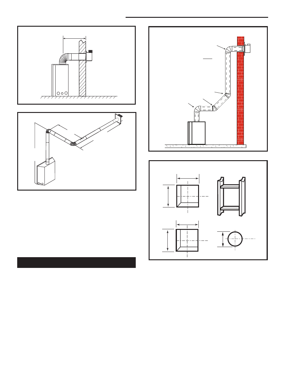
Fig. 41 Maximum horizontal vent run.
7.5'
(2.3m)
A
B
A + B = 17' (5.2m) Max.
1 x 90° elbow in horizontal plane = 3’ (914mm)
FP1238
Fig. 42 Maximum vent run with elbows.
1
2
3
4
Example:
Elbow 1 = 90°
Elbow 2 = 45°
Elbow 3 = 45°
Elbow 4 = 90°
Total angular variation = 270°
1 + 2 + 3 + 4 = 270°
FP1239
Fig. 43 Maximum number of elbow degrees.
STEP 1
Locate vent opening on the wall. It may be necessary
to first position the fireplace and measure to obtain hole
location. Depending on whether the wall is combustible
or noncombustible, cut opening to size. (Fig. 44)
For combustible walls first frame in opening.
Combustible Walls: (Fig. 44) Cut a 9³⁄₈”H x 9³⁄₈”W (240
x 240 mm) hole through the exterior wall and frame as
shown.
Noncombustible Walls: (Fig. 44) Hole opening must
be 7¹⁄₂” (190 mm) in diameter.
Vertical Sidewall Installations
VO584-100
Vent Opening
2/99 djt
Vent Opening for Combustible Wall
9³⁄₈”
(240mm)
9³⁄₈”
(240mm)
Fireplace Hearth
Framing
Detail
Opening for Noncombustible Wall
7¹⁄₂”
(190mm)
VO584-100
Fig. 44 Locate vent opening on wall.
STEP 2
Place fireplace into position. (Fig. 45) Measure the verti-
cal height (X) required from the base of the flue collars
to the center of the wall opening.
STEP 3
Using appropriate venting component(s) attach to
fireplace with three (3) screws. (Fig. 46) Follow with the
installation of the inner and outer elbow. Again secure
joints with three (3) sheet metal screws.
STEP 4
Measure the horizontal length requirement including
a 2” (51 mm) overlap, ie from the elbow to the outside