Cdv series direct vent gas fireplace, Below grade installations, Vertical through-the-roof applications – Vermont Casting 36CDVRRN User Manual
Page 24
24
CDV Series Direct Vent Gas Fireplace
20010175
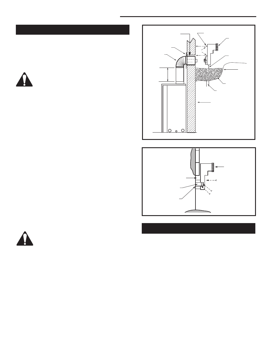
Below Grade Installations
When it is not possible to meet the required vent ter-
minal clearances of 12” (305 mm) above grade level a
snorkel vent kit is recommended. It allows installation
depth of down to 7” (178 mm) below grade level. The
7” is measured from the center of the horizontal vent
pipe as it penetrates through the wall.
If venting system is installed below
ground, we recommend a window well with
adequate and proper drainage.
Ensure sidewall venting clearances are observed.
If installing a snorkel a minimum 24” (610 mm) vertical
rise is necessary. The maximum horizontal run with
the 24” (610 mm) vertical pipe is 36” (914 mm). This
measurement is taken from the collar of the fireplace (or
transition elbow) to the face of the exterior wall. Refer to
the Sidewall Vent Graph for extended horizontal run if
the vertical rise exceeds 24” (610 mm).
1. Establish vent hole through the wall. (Fig. 44)
2. Remove soil to a depth of approximately 16” (406 mm)
below base of snorkel. Install drain pipe. Install win-
dow well (not supplied). Refill hole with 12” (305 mm)
of coarse gravel leaving a clearance of approximately
4” (102 mm) below snorkel. (Fig. 49)
3. Install vent system.
4. Ensure a watertight seal is made around the vent pipe
coming through the wall.
5. Apply high temperature sealant caulking around the 4”
and 7 “ snorkel collars.
6. Slide the snorkel into the vent pipes and secure to the
wall.
7. Level the soil to maintain a 4” (102 mm) clearance
below snorkel. (Fig. 49)
BG402a
Top Vent
Below grade installation
1/26/00 djt
Firestop
7” Pipe
7TDVSNORK
(Snorkel)
4” (102mm)
Clearance
Min.
Window
Well
Gravel
Drain
BG402
Fig. 49 Below grade installation.
Zero Clearance Sleeve
(if required)
*A minimum of 24” (610mm) ver-
tical pipe must be installed when
using the 7TDVSNORK Kit.
*The 22” (559mm) vertical rise
(center to center) of the snorkel
may be included for calculationof
max. horizontal run.
24” (610mm)
Minimum*
Screws
Foundation Wall
Do not back fill around snorkel. A clearance
of at least 4” (102 mm) must be maintained
between snorkel and the soil.
If the foundation is recessed, use recess brackets (not
supplied) for securing lower portion of the snorkel.
Fasten brackets to wall first, then secure to snorkel
with self drilling #8 x 1/2 sheet metal screws. It will be
necessary to extend vent pipes out as far as protruding
wall face. (Fig. 50)
BG401
Snorkel
2/10/99 djt
Foundation Recess
Snorkel
Wall Screws
Recess Brackets
Watertight Seal
Around Pipe
Sheet Metal
Screws
BG401
Fig. 50 Snorkel installation, recessed foundation.
Vertical Through-the-Roof Applications
This Gas Fireplace has been approved for:
•
Vertical installations up to 40’ (12 m) in height. Up
to a 10’ (3 m) horizontal vent run can be installed
within the vent system using a maximum of two 90°
elbows. (Fig. 51)
•
Up to two 45° elbows may be used within the
horizontal run. For each 45° elbow used on the
horizontal level the maximum horizontal length must
be reduced by 18” (457 mm).
Example: Maximum horizontal length
0 x 45° elbows = 10’ (3 m)
1 x 45° elbows = 8¹⁄₂’ (2.6 m)
2 x 45° elbows = 7’ (2.1 m)
•
A minimum of an 8’ (2.4 m) vertical rise.