Cdv series direct vent gas fireplace, Below grade installations – Vermont Casting 36CDVRRN User Manual
Page 18
18
CDV Series Direct Vent Gas Fireplace
20010175
STEP 5
Guide the vent termination’s 4” and 7” collars into their
respective vent pipes. Double check that the vent pipes
overlap the collars by 2” (51 mm). Secure the termination
to the wall with screws provided and caulk around the
wall plate to weatherproof. (Fig. 30)
STEP 6
Support the horizontal pipes every 36” (914 mm) with
metal pipe straps. Make sure that the horizontal vent
pipe is installed on a level horizontal plane.
STEP 7
Re-check the fireplace to make sure that it is levelled,
properly positioned, and nailed or screwed to the floor.
If applied, the fireplaces adjustable frame drywall strips
(nailing flanges) should be fastened. Refer to “Framing
& Finishing”.
CFM138
4", 7" collar
2/26/01 sta
X
X
CFM138
Fig. 30 Horizontal length requirement.
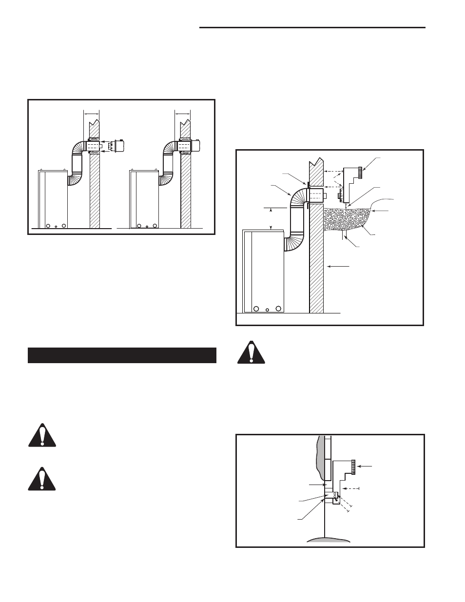
Below Grade Installations
When it is not possible to meet the required vent ter-
minal clearances of 12” (305 mm) above grade level
a snorkel vent kit #7TDVSNORK is required. It allows
installation depth of down to 7” (178 mm) below grade
level. The 7” is measured from the center of the hori-
zontal vent pipe as it penetrates through the wall.
If venting system is installed below
ground, we recommend a window well with
adequate and proper drainage.
Ensure sidewall venting clearances are observed.
The maximum horizontal run with 24”
vertical rise is 36” (914 mm) from the
back of the fireplace to the face of the
exterior wall. See vent graph (Page 12) for
extended horizontal run if the vertical rise
exceeds 24” (610 mm).
1. Establish vent hole through the wall. (Fig. 13)
2. Remove soil to a depth of approximately 16”
(406mm) below base of snorkel. Install window
Do not back fill around snorkel. A
clearance of at least 4” (102 mm) must be
maintained between the snorkel and the
soil.
BG401
Snorkel
2/10/99 djt
Foundation Recess
Snorkel
Wall Screws
Recess Brackets
Watertight Seal
Around Pipe
Sheet Metal
Screws
BG401
Fig. 32 Snorkel installation, recessed foundation.
BG400
Below grade installation
2/10/99 djt
10/19/99 added standoffs
24" (610mm)
Minimum*
Firestop
7” Pipe
7TDVSNORK
(Snorkel)
4” (102mm)
Clearance
Min.
Window
Well
Gravel
Drain
Foundation Wall
BG400
Fig. 31 Below grade installation.
*A minimum of 24” (608mm)
vertical pipe must be installed
when using 7TDVSNORK Kit.
If the foundation is recessed, use recess brackets (not
supplied) for securing lower portion of the snorkel.
Fasten brackets to wall first, then secure to snorkel
with self drilling #8 x 1/2 sheet metal screws. It will be
necessary to extend vent pipes out as far as protruding
wall face. (Fig. 32)
well (not supplied). Refill hole with 12” (305 mm) of
coarse gravel leaving a clearance of approximately
4” (102 mm) below snorkel. (Fig. 31)
3. Install vent system. See Page 12, Steps 2 through 5.
4. Ensure a watertight seal is made around the vent
pipe coming through the wall.
5. Apply high temperature sealant caulking around the
4” and 7” snorkel collars.
6. Slide into the vent pipe and secure to the wall.
7. Level the soil to maintain a 4” (102 mm) clearance
below snorkel. (Fig. 31)