Cdv series direct vent gas fireplace – Vermont Casting 36CDVRRN User Manual
Page 20
20
CDV Series Direct Vent Gas Fireplace
20010175
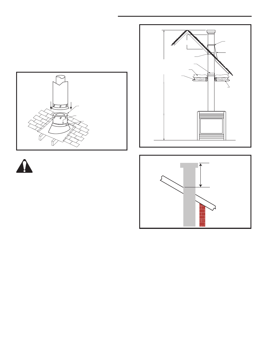
7. Install roof support (Fig. 36 & 37) and roof flashing
making sure upper flange is below the shingles. (Fig.
36)
8. Install appropriate pipe sections until the venting is
above the flashing. (Fig. 36)
9. Install storm collar and seal around the pipe.
10. Add additional vent lengths for proper height. (Fig
38)
TWL101a
Twist Lock Pipe
2/8/99 djt
3 #5 Sheet Metal
Screws per Joint
Storm Collar
TWL101a
Fig. 36 Roof flashing.
Sealant
FP1022
Typical Straight Up Installation
1/26/00 djt
50’
(15 m)
Storm Collar
Roof Flash-
ing
Vent
Termination
Roof
2’ Min.
Roof Support
Attic Insulation
Shield
Attic
Insulation
Joists
Joists
FP1022
Fig. 37 Typical straight-up installation.
Min.
2' (610 mm)
FP1185
Fig. 38 Minimum termination to roof clearance.
The enlarged ends of the vent section
always face down. (Fig. 36)