Cdv series direct vent gas fireplace, Vertical through-the-roof applications, Vertical through-the-roof installation – Vermont Casting 36CDVRRN User Manual
Page 19
19
CDV Series Direct Vent Gas Fireplace
20010175
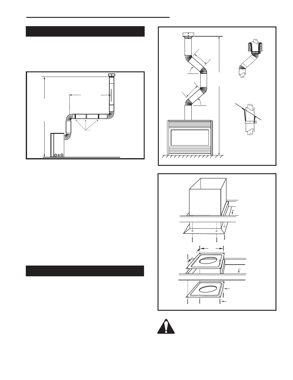
Vertical Through-the-Roof Applications
CFM148
Maximum
10’
(3 m)
Minimum
8’ (2.4 m) /
Maximum
40’ (12 m) Vertical
Rise
CFM148
Pipe Straps Every
3’ (914 mm)
Fig. 33 Support straps for horizontal runs.
This Gas Fireplace has been approved for:
1. Vertical installations up to 40’ (12 m) in height. Up to
10’ (3 m) horizontal vent run can be installed within
the vent system using a maximum of three 90°
elbows.
2. Up to two 45° elbows may be used within the
horizontal run. For each 45° elbow used on the
horizontal level the maximum horizontal length must
be reduced by 18” (457 mm).
Example: Maximum horizontal length
0 x 45° elbows = 10’ (3 m)
1 x 45° elbows = 8¹⁄₂’ (2.6 m)
2 x 45° elbows = 7’ (2.1 m)
3. A minimum of an 8’ vertical rise.
4. Two sets of 45° elbows offsets within these vertical
installations. From 0 to a maximum of 8’ (2.4 m) of
vent pipe can be used between elbows. (Fig. 34)
5. 7DVCS must be used to support offsets. (Fig. 34)
This application will require that you first determine
the roof pitch and use the appropriate 7DVSKV (A, B
or F). (Refer to Venting Components List, Page 27)
FP1021
Typical vertical
through the roof
application
3/26/00 djt
Max.
8’
(2.4 m)
45°
Max.
8’
(2.4 m)
45°
50’
(15 m)
Typical
Ceiling
Support
Application
Typical Roof
Support Ap-
plication
FP1021
Typical Offset Installation
Fig. 34 Typical vertical roof applications.
Vertical Through-the-Roof Installation
1. Locate your fireplace.
2. Plumb to center of the (4”) flue collar from ceiling
above and mark position.
3. Cut opening equal to 9³⁄₈” x 9³⁄₈” (240 x 240 mm).
4. Proceed to plumb for additional openings through
the roof. In all cases, the opening must provide a
minimum of 1 inch clearance to the vent pipe, i.e.,
the hole must be at least 9³⁄₈” x 9³⁄₈” (240 x 240 mm).
5. Place fireplace into position.
6. Place firestop(s) #7DVFS or Attic Insulation Shield
#7DVAIS into position and secure. (Fig. 35)
CFM100
Firestop-Vertical
09/20/00
11"
11"
Joist
Joist
Firestop Spacer
Nails (4)
Upper Floor
Attic Insulation
Shield
Ceiling
Installation
CFM100
Fig. 35 Place firestop spacer(s) and secure.
If there is room above ceiling level,
firestop spacer must be installed on both
the bottom and the top side of the ceiling
joists. If an attic is above ceiling level a
7DVAIS (Attic Insulation Shield) must be
installed. (Fig. 35)