Setting up symbols, Environmental protection – Triton TCM PL User Manual
Page 6
6
GB
REMOVING OR INSTALLING PLANER BLADES
CAUTION. Always ensure that the tool is switched off
and unplugged from the power supply before installing or
removing blades.
Your planer is fitted with reversible blades.
Blades can be reversed when blunt. After both sides of the
blades have been used they should be discarded.
NOTE. These blades cannot be re-sharpened.
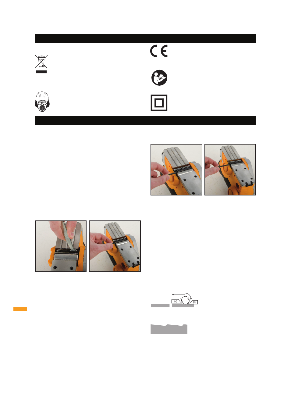
REMOVING A PLANER BLADE
1. Using Spanner (8), loosen the three Clamping Screws
(10).
2. Slide the Planer Blade (9) from the slot in the Blade
Barrel (11).
INSTALLING A PLANER BLADE
1. Either turn over the Planer Blade (9) or replace it if
required.
2. Slide the good blade face up into the blade support
block of the Blade Barrel (11).
NOTE. The ridge along the blade should be on the blade
face on the opposite side to the Clamping Screws (10).
3. Tighten the Clamping Screws (10), ensuring they are
tightened evenly.
4. Repeat for the second blade.
NOTE. Always change both blades at the same time,
otherwise the resulting imbalance can cause vibration and
shorten the blade and tool life.
CAUTION. When installing blades, first clean out all chips
or foreign matter adhering to the Blade Barrel (11) and the
blades themselves. Use blades of the same dimensions
and weight, or the barrel will oscillate and vibrate, causing
poor planing action and possibly a machine breakdown.
Tighten the Clamping Screws (10) carefully when attaching
the blades to the planer. A loose clamping screw could
be extremely dangerous. Regularly check to see they are
tightened securely.
NOTE. Your planing surface will be rough and uneven if the
blades are not correctly set. The blades must be mounted
so that the cutting edge is absolutely level, i.e. parallel to
the surface of the Fixed Rear Base (3).
The examples below show correct and incorrect settings:
Clean smooth cut
Nicks in surface – caused by the edge of one or all blades
not being parallel to the rear base line.
Gouging at start – caused by the edge of one or all blades
not protruding enough in relation to the rear base line.
SETTING UP
SYMBOLS
ENVIRONMENTAL PROTECTION
Waste electrical products should not be
disposed of with household waste. Please
recycle where facilities exist. Check with your
local authority or retailer for recycling advice
Always wear ear, eye and respiratory
protection
Conforms to relevant legislation
and safety standards
Do not use before viewing and
understanding the full operating
instructions
Double insulated for additional
protection
Symbols / Setting Up
773123_manual with Japanese.indd 6
26/08/2014 15:24