Before use – Triton TA 235CSL User Manual
Page 8
7
GB
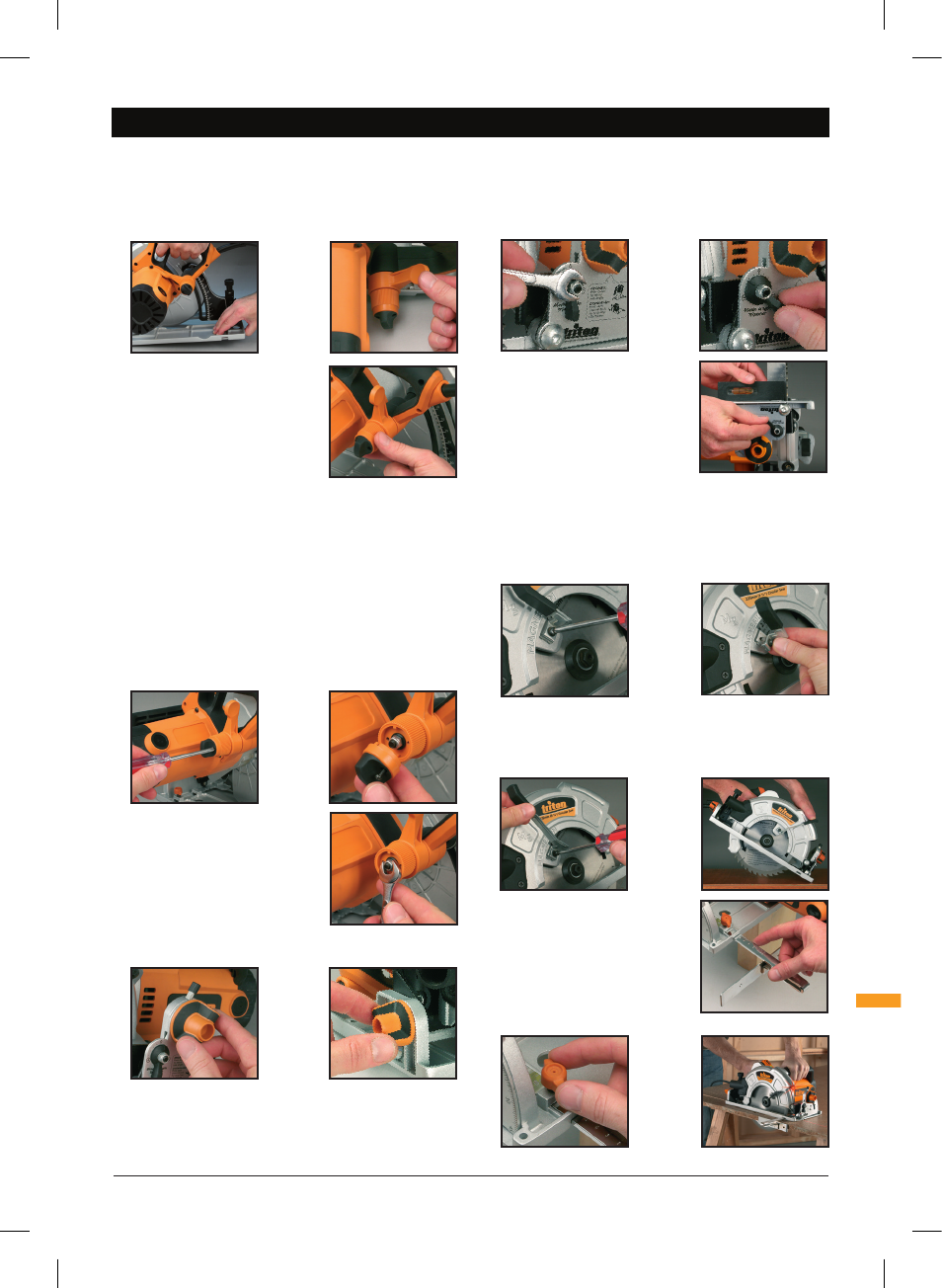
BEFORE USE
Before Use
ADJUSTING THE CUTTING DEPTH
Ensure that the tool is switched off and disconnected from the power supply before
making any adjustments or installing or removing blades.
1. Loosen the Depth Adjustment Locking Lever (24) and lift the back of the saw
away from the baseplate until the approximate depth is achieved. Push down on
the lever to lock the saw in position.
2. For fine depth adjustments, lock the saw at the
approximate depth and then turn the micro depth
adjustment knob for the exact depth. Turn the
micro depth adjustment knob in a clockwise
direction to decrease the depth of cut, turn in an
anti-clockwise direction to increase the depth of
cut. The adjustment range is 6mm, if insufficient,
reset the main depth adjustment, and fine tune
again. The micro-adjustment knob must be set
to full depth to achieve the 82mm maximum
depth of cut.
3. The circular saw also features a rack & pinion depth adjustment feature. The
rack & pinion depth adjustment is most useful when the saw is mounted below a
Triton Workcentre.
4. To adjust the depth using the rack & pinion feature loosen the Depth Adjustment
Locking Lever (24) and then turn the Rack & Pinion Adjustment Knob (23) to
adjust the cutting height. Turn the knob in an anti-clockwise direction to increase
the cutting depth, turn in a clockwise direction to decrease the cutting depth.
Tighten the depth adjustment locking lever to lock the saw in position.
ADJUSTING THE DEPTH LOCKING LEVER TENSION
If the Depth Adjustment Locking Lever (24) is not providing enough tension adjust
as follows:
1. Loosen and remove the 2 Phillips head screws that secure the Rack & Pinion
Adjustment Knob (23). Remove the adjustment knob, this will reveal the locking
lever tension nut.
2. Using a 10mm wrench tighten the tension nut
in a clockwise direction to increase the tension
of the Depth Adjustment Locking Lever (24).
3. Once the locking lever is providing sufficient
tension replace the adjustment knob and secure
using the 2 Phillips head screws.
4. Check the operation of the locking lever before
operating the saw.
ADJUSTING THE BEVEL ANGLE
1. Bevel angles can be set anywhere within the range 0° to 47°. Pre-set stops are
available at 0°, 15°, 22.5°, 30° and 45° for quick, accurate bevel settings.
2. Loosen the Front and Rear Bevel Lock Knobs (13 and 4) and depress the Bevel
Detent Latch (12). Pivot the saw to the angle you require then release the detent
latch. A small movement of the saw motor will allow the latch to pop up into the
detent position. Tighten both bevel lock knobs.
3. For selecting other angles, leave the detent latch disengaged by pushing it down
and back towards the motor, where it has a ‘lock-out’ position. Firmly tighten
both knobs at the required angle.
FINE-TUNING BEVEL ANGLE & STOPS
1. You can fine-tune the calibration scale and the bevel detent positions by +/-2˚.
2. Make sure the saw is set at 0˚ and the bevel detent latch is engaged.
3. Loosen the rear Bevel Lock Knob (4), also
loosen the Nyloc nut on the Bevel Micro
Adjustment Lever (15) using a 10mm spanner.
4. Adjust the trimmer to the left or right until the
blade is square to the baseplate or to the Triton
table.
5. Tighten the rear bevel lock knob and Nyloc nut
after any adjustments.
Note: For full trim range adjustment ensure the blade
depth is set 2–3mm below maximum, for motor clearance. Full depth can be re-set
once the adjustment has been made.
BLADE GUARD LEVER
For plunge or pocket cuts, use the Long Blade Guard Lever (21). To change the lever
follow the below instructions:
1. Loosen and remove the Phillips head screw holding the Short Blade Guard Lever
(5). Also remove the blade guard lever.
2. Fit the Long Blade Guard Lever (21) into the same position.
3. Replace the Phillips head screw and tighten to secure the long blade guard lever
in position.
4. The long blade guard lever can now be used to provide better control of the lower
guard when performing pocket cuts.
RIP FENCE ADJUSTMENT
1. The Rip Fence (17) can be used on the left
or the right of the blade. Using the rip fence
provides accurate cuts without the need to work
free-hand following pencil lines.
2. Locate the rip fence into the mounting slots
at the front of the Base Plate (6) and tighten
the Locking Knob (18) to lock it at the required
cut width. For greater width setting, the thumb
screw can be repositioned to the inner or outer clamp location.
TA235CSL_Z5MANPRO1_V2.indd 7
06/11/2013 12:23